-
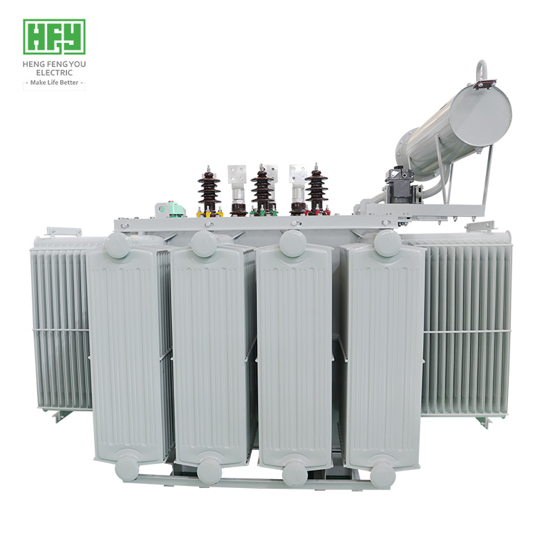
Maximum Practical 0.4 kV Distribution Capacity: The 20 MVA rating extracts the absolute maximum power from a 0.4 kV LV system. Benefits include:
-
Single transformer solution for very large loads—simplifies protection coordination
-
Reduced footprint compared to multiple smaller transformers
-
Lower total installed cost than multi-transformer alternatives
-
Simplified maintenance (one unit vs. multiple)
-
Ultra-High Efficiency (>99.3%): The 20 MVA transformer achieves full-load efficiency exceeding 99.3% , surpassing European Ecodesign Directive 2015/2014/548/EC Tier 2 requirements. No-load losses are minimized to 14–20 kW, while load losses are optimized through continuously transposed conductors (CTC) and optimized conductor geometry. Over a 25-year lifespan, this efficiency translates to millions of dollars in cumulative energy savings.
-
Extreme Short-Circuit Withstand (IEC 60076-5): At 20 MVA, the electromagnetic forces during a bolted secondary-side fault can exceed 160 kN on the LV windings. Our transformers feature:
-
Heavy-duty axial clamping rings machined from high-strength G10 epoxy laminate
-
Continuously transposed conductor (CTC) windings for optimal current distribution and reduced eddy losses
-
Pre-compressed disc-type winding construction with radial spacers at 35mm intervals
-
Stainless steel end-block banding to prevent telescoping
All designs are type-tested for short-circuit withstand per IEC standards.
-
Advanced Thermal Management (ODAF Standard): The 20 MVA unit generates substantial heat (typically 80–115 kW total losses). Our cooling systems include:
-
ODAF (standard): Oil-directed, air-forced cooling—directing oil flow precisely to winding hotspots
-
Water cooling (recommended for high ambient temperatures): Oil-water heat exchangers for environments >45°C
-
Multiple independent cooling circuits for redundancy (n-1 operation)
Fiber-optic winding hotspot monitoring is standard equipment.
-
Hermetically Sealed, Maintenance-Free Tank (IP65): The fully welded, sealed tank prevents moisture ingress and oil oxidation. Designed for a 25-year service life with zero routine oil intervention.
-
Vacuum-Type On-Load Tap Changer (OLTC) – Standard Equipment: Vacuum-type OLTCs from leading manufacturers (MR, ABB, or equivalent) are included as standard, enabling real-time voltage regulation across a ±10% range in 32 steps for precise voltage control.
-
Comprehensive Monitoring Suite (Standard): Each 20 MVA transformer ships with:
-
Winding Temperature Indicator (WTI) with alarm and trip contacts
-
Oil Temperature Indicator (OTI) with maximum pointer
-
Buchholz Relay with dual float and surge contacts
-
Pressure Relief Valve (PRV) with visual indicator
-
Oil Level Gauge with low-level alarm contact
-
DGA Sampling Port for dissolved gas analysis
-
Partial Discharge (PD) Sensor port (standard)
-
Online bushing monitoring port (optional)
-
Eco-Friendly Fluid Compatibility: Available with FR3 Natural Ester Fluid for enhanced fire safety (fire point > 360°C), extended insulation life (up to 8x longer), and full biodegradability.
-
Global Certification Portfolio: Certified to ISO 9001, CE, IECEE CB Scheme, SABS, COC, CSA, UL, and GOST.
V. Frequently Asked Questions (FAQ) — Pain Points Unique to 20 MVA Class
Q1: Is 20 MVA at 0.4 kV really practical? Should I consider a higher LV voltage?
At 28,867 A, 0.4 kV distribution reaches its practical limit. Consider:
-
Stay at 0.4 kV if: Your existing switchgear and loads are already at 0.4 kV, and total load is 16–18 MVA (leaving headroom)
-
Consider 690 V if: You are designing a new facility and total load exceeds 18 MVA—690 V halves the current to ~16,700 A
-
Consider 3.3 kV or 6.6 kV if: Load exceeds 25 MVA or distances exceed 500m
-
Split option: Two 10 MVA transformers at 0.4 kV may be simpler than one 20 MVA unit
We provide feasibility studies to help you make this decision.
Q2: How do I manage the extreme LV current of 28,867 A?
This is the single biggest challenge of the 20 MVA 0.4 kV configuration:
-
Busbar system: 6–8 parallel runs of 120×12 mm copper busbars per phase
-
Busbar cooling: Forced air cooling of busbar enclosures may be required
-
ACB rating: Air circuit breaker rated for 30,000–40,000 A (specialized equipment)
-
Connection: Direct busbar coupling between transformer and main switchboard
-
Skin effect: Busbar thickness limited to 12mm max; multiple thinner bars preferred
-
Thermal imaging: Mandatory during commissioning to verify all joints
We provide complete LV connection design with each transformer.
Q3: What are the civil works requirements for a 20 MVA transformer?
-
Foundation: Reinforced concrete pad capable of supporting 32+ tons
-
Oil containment pit: Sized to contain 110% of oil volume (7,700–11,000 liters)
-
Fire protection: Automatic fire suppression system (water spray, foam, or inert gas)
-
Clearances: Minimum 1.5m from walls on all sides; 2m overhead clearance
-
Cable trenches: Sized for multiple parallel busbar runs or cable trays
-
Crane access: Clear path for 50-ton crane during installation and future replacement
We provide detailed civil works drawings with each order.
Q4: What is the recommended protection scheme for a 20 MVA transformer?
Comprehensive protection is mandatory:
-
Primary protection: Transformer differential protection (87T) – mandatory
-
Backup protection: Directional overcurrent (67), restricted earth fault (64REF)
-
HV side: Vacuum circuit breaker with overcurrent, earth fault, and undervoltage protection
-
LV side: Air circuit breaker with LSI trip unit, ground fault, and zone interlocking
-
Transformer body: Buchholz relay, PRV, WTI, OTI, oil level gauge
-
System protection: Surge arrestors, neutral grounding resistor, ground resistance ≤ 2Ω
-
Advanced: Online DGA monitor, partial discharge monitoring, bushing condition monitoring
We provide a complete protection philosophy document with each transformer.
Q5: Can I parallel two 20 MVA transformers?
Yes, but with important caveats:
-
Identical design: Both units must be identical (same manufacturer, same design)
-
Impedance tolerance: Z% must match within ±2.5%
-
OLTC synchronization: Required for automatic load sharing
-
Circulating current: Must be verified by calculation
-
Space requirements: Substantial additional footprint needed
For most applications, a single 20 MVA unit is preferred over paralleled smaller units.
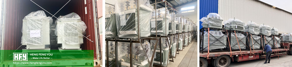
Q6: What are the transport challenges for a 20 MVA transformer?
-
Weight: 24,000–32,000 kg filled—requires specialized heavy-haul transport
-
Dimensions: May exceed standard road width/height limits
-
Solutions:
-
Ship without oil (reduces weight by 7,000–9,000 kg)
-
Use specialized transformer transport trailer with hydraulic suspension
-
Route survey required (bridge clearances, road widths, turning radii)
-
Transport permits: Allow 4–6 weeks for permitting
-
Rail transport: Preferred for long-distance domestic delivery
-
Crane: ≥ 50 tons capacity at destination
Q7: What is the expected noise level, and what mitigation options exist?
-
Standard design (ODAF): 82–88 dB(A) at 1 meter
-
Low-noise core design: 74–80 dB(A) (reduced flux density, premium core steel, step-lap joints)
-
Acoustic enclosure: Reduces external noise by 25–35 dB(A)
-
Vibration isolation: Spring mounts reduce structure-borne noise
-
Fan silencers: Reduce fan noise contribution by 5–8 dB(A)
For noise-sensitive environments, acoustic enclosure is strongly recommended.
Q8: What is the recommended DGA monitoring strategy?
As a critical high-value asset:
-
Continuous online DGA monitor: Mandatory (cost: $8,000–$15,000)
-
Key gas thresholds (IEC 60599):
-
H₂ > 100 ppm: Investigate
-
C₂H₂ > 3 ppm: Immediate action required
-
CO > 500 ppm: Paper degradation possible
-
CO₂ > 4,000 ppm: Accelerated aging
-
Sampling frequency:
-
Interpretation: Duval Triangle and Duval Pentagon analysis with each report
-
Action plan: We provide a comprehensive DGA response protocol
Q9: What is the recommended maintenance schedule?
-
Continuous (SCADA): Oil temperature, load current, OLTC position, alarm status, DGA trends
-
Daily: Remote monitoring review
-
Weekly: Visual inspection (leaks, oil level, fan operation, noise)
-
Monthly: Infrared thermography of all connections
-
Quarterly: Bushing capacitance/power factor, tap changer inspection, DGA laboratory confirmation
-
Annually: Insulation resistance (IR), polarization index (PI), winding resistance, turns ratio, sweep frequency response analysis (SFRA)
-
Every 3 years: Full oil dielectric test, furan analysis, partial discharge measurement
-
Every 10 years: Internal inspection, core bolt insulation test, tank integrity pressure test
Q10: What warranty and post-sale support do you offer?
-
Standard warranty: 36 months from commissioning or 39 months from Bill of Lading (extended for this capacity class)
-
Extended warranty: Up to 7 years (includes annual DGA analysis, remote monitoring, priority technical support, and one on-site inspection per year)
-
Spare parts commitment: Guaranteed availability for minimum 25 years
-
Technical support: 24/7 dedicated hotline; on-site commissioning supervision included
-
Training: Comprehensive operator and maintenance training program (documentation + on-site session + follow-up virtual sessions)
-
Service network: Authorized service partners in 40+ countries for rapid response
-
Performance guarantee: Guaranteed efficiency and loss values with penalties for non-compliance
Grow Your Business with Hengfengyou Electric
Our vision is to become the world's most trusted manufacturer of power transformers from 50 kVA to 50 MVA+. With decades of engineering excellence, thousands of successful large-capacity deliveries across 50+ countries, and an unwavering commitment to quality, Hengfengyou Electric delivers transformers that power the world's most critical infrastructure—reliably, efficiently, and sustainably.