HENGFENGYOU ELECTRIC --SMART ELECTRIC GLOBAL SERVICE PROVIDER



A large-scale solar power plant is not a simple connection of modules to the power grid. Direct current generated by solar modules is converted into alternating current via inverters. The AC power then needs to be stepped up by boost transformers and collected through medium-voltage collection lines to the main substation.
Typical electrical path: Solar modules → Solar inverters → 0.4kV AC side → 33kV boost transformer → 33kV collection lines → Main substation → Power grid
For large-scale solar projects in Saudi Arabia, equipment selection shall address multiple challenges simultaneously:
Therefore, solar projects require not merely a standalone transformer, but a complete boost solution compatible with inverters, medium-voltage collection systems and main substations.
1250kVA, 33/0.4kV is a typical boost configuration widely adopted in large-scale solar power plants.
Its core function is to step up 0.4kV alternating current output from inverters to 33kV, and feed power into the medium-voltage collection network of the solar site.
Typical specifications:
| Item | Typical Parameter |
|---|---|
| Application | Large-scale solar power plant |
| Transformer Capacity | 1250kVA |
| High-Voltage Side | 33kV |
| Low-Voltage Side | 0.4kV |
| Frequency | 50Hz |
| Transformer Type | Oil-immersed boost transformer |
| Cooling Mode | ONAN |
| Medium-Voltage Equipment | 33kV switchgear |
| Low-Voltage Equipment | 0.4kV power distribution equipment |
| Installation | Outdoor containerized |
It should be noted that 1250kVA is not a fixed standard capacity for all solar projects. The final capacity shall be determined according to inverter rated power, quantity, maximum AC output, operating temperature, load factor and project design requirements.
In practical projects, instead of simply questioning whether 1250kVA is sufficient, it is more important to confirm the inverter model and its AC-side parameters.
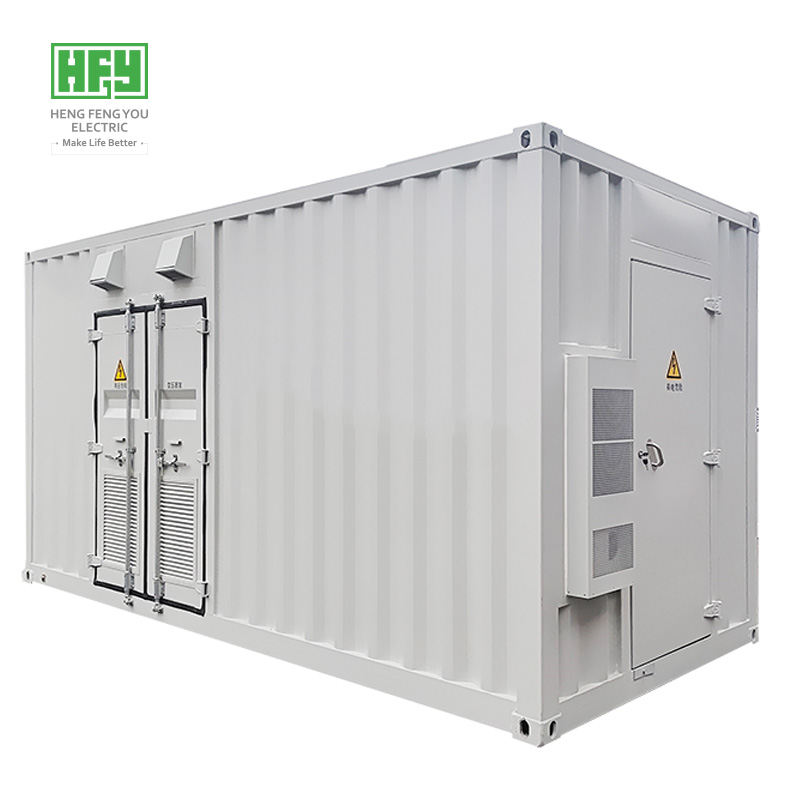
In this typical solution, AC output from one or multiple solar inverters connects to the low-voltage side of the containerized substation. Power is stepped up to 33kV via the 1250kVA boost transformer.
Multiple boost units are then linked to a collection substation or main substation through 33kV collection lines.
The major advantage of this topology is that boost equipment can be placed close to solar arrays and inverters, shortening low-voltage cable runs.
For a given transmission power, higher voltage reduces current in the circuit, which helps cut I²R loss of collection lines. Therefore, for solar plants occupying large land areas, a 33kV medium-voltage collection system is generally more reasonable than long-distance low-voltage transmission.
Nevertheless, the specific collection voltage shall be defined based on project scale, line length, short-circuit capacity, cable configuration and grid connection requirements.
This is a common pain point in solar container transformer selection.
Capacity cannot be calculated simply by dividing total solar plant installed capacity by the number of container transformers. Priority shall be given to the actual AC output capability of inverters.
For example, when one boost unit serves multiple inverters, the following parameters need verification:
Undersized transformers will suffer increased temperature rise under heavy load. Oversized transformers raise capital cost and reduce the economic operating efficiency of equipment.
In this sense, 1250kVA is a typical specification in project design, rather than a capacity value set independently from inverter parameters.
Ambient temperature is a critical factor for transformer selection for Saudi projects.
Losses generated during long-term transformer operation are converted into heat. High ambient temperature impairs heat dissipation, so the temperature rise margin and operating conditions of the same transformer vary under different ambient temperatures.
Design considerations for Saudi solar container transformers:
For high-temperature solar projects in Saudi Arabia, the focus is not simply labeling equipment as “high-temperature resistant”, but verifying transformer capacity, temperature rise and heat dissipation schemes against site ambient temperature.
A practical challenge in desert regions: equipment requires heat dissipation, yet heavy ventilation increases the risk of sand and dust ingress.
Containerized substations must strike a balance between dust protection and heat dissipation.
Key design measures:
For long-running large-scale solar projects, dust-proof design affects not only equipment service life, but also the frequency of subsequent maintenance.
The 1250kVA transformer is only one component of the whole boost unit.
On the 33kV side, corresponding medium-voltage switchgear shall be configured to match collection lines and protection schemes, forming the power path: Transformer → 33kV switchgear → Collection lines → Collection substation
Key parameters to verify during medium-voltage equipment selection:
If a project contains multiple solar boost units, the quantity of switchgear and cable routing shall be determined together with the 33kV collection line topology.
A complete solar containerized substation covers medium-voltage system parameters beyond the single 1250kVA transformer specification.
Large-scale solar projects are characterized by massive equipment quantities, tight schedules and remote site locations. If most equipment is installed and wired piece by piece on site, construction workload rises and uncertainties in commissioning increase.
Containerized substations enable factory integration and pre-assembly of most equipment, including:
After delivery to the project site, major work only includes foundation positioning, external cable connection and on-site commissioning.
For large solar projects requiring batch deployment of dozens or even hundreds of boost units, this standardized model reduces repetitive on-site construction and accelerates project execution.
Moreover, FAT (Factory Acceptance Test) completed before shipment helps detect assembly and wiring defects in advance, lowering on-site commissioning risks.
To meet boost demands of large-scale solar power plants in Saudi Arabia, Hengfenyou Electric provides 1250kVA 33/0.4kV containerized substation solutions integrating boost transformers, 33kV medium-voltage switchgear, 0.4kV low-voltage power distribution and auxiliary systems.
Customized design can be implemented according to actual project conditions in the following aspects:
Hengfenyou Electric matches container transformer capacity and internal equipment according to inverter models, solar plant capacity, 33kV collection schemes and local environmental conditions, instead of applying one fixed standard configuration to all projects.
If customers have a preliminary project proposal, the following information can be provided for fast technical evaluation and quotation:
If only solar plant capacity, inverter model and 33kV collection voltage are available, customers can provide this basic information. Hengfenyou Electric will further assist in confirming transformer capacity and containerized substation configuration.
Q1: Is 1250kVA 33/0.4kV a standard configuration for solar projects in Saudi Arabia? A1: No. 1250kVA 33/0.4kV is a typical configuration. Actual capacity and voltage level shall be determined by inverter parameters, project scale, collection system and local grid connection requirements.
Q2: Why is voltage stepped up to 33kV after inverters output 0.4kV? A2: Stepping up to 33kV reduces current at the given transmission power, which helps cut power loss of medium-voltage collection lines and meets centralized power collection requirements for large solar sites.
Q3: Will high temperature in Saudi Arabia cause derating of the 1250kVA transformer? A3: High ambient temperature impairs equipment heat dissipation and temperature rise. Whether derating is required shall be calculated against specific ambient temperature, transformer design, cooling method and project technical specifications, and cannot be judged merely by a temperature value.
Q4: Can containerized substations integrate transformers and 33kV switchgear in one unit? A4: Yes. Subject to project design, containerized substations can integrate transformers, medium-voltage switchgear, low-voltage power distribution devices and auxiliary systems. The layout shall be designed considering equipment dimensions, heat dissipation, cable routing and maintenance space.
Q5: Can Hengfenyou Electric design container transformers based on inverter models? A5: Yes. After customers provide inverter models, AC output parameters, project capacity and target collection voltage, we can configure transformer capacity and supporting medium-voltage equipment accordingly.
Q6: Why are prefabricated container substations suitable for large-scale solar projects? A6: The primary advantage is that most assembly, inspection and testing work can be completed in factory. After arrival on site, repetitive installation and wiring work is reduced. For large solar projects with numerous equipment units and tight construction schedules, this solution improves on-site installation efficiency and lowers commissioning risks.
For large-scale solar power plants in Saudi Arabia, containerized substation selection shall not focus only on transformer capacity. Inverter matching, high-temperature operation, sand dust protection, 33kV power collection, equipment integration and on-site installation conditions must all be considered.
1250kVA 33/0.4kV can serve as a typical solar boost unit, but the final solution shall be built on specific project parameters. Integrated design of transformers, medium-voltage switchgear and auxiliary systems enables the boost and collection system of solar fields to better match actual project demands.
Hengfenyou Electric specializes in power transmission and distribution equipment and overseas project support. We can provide customized transformer and containerized substation solutions according to different solar project capacities, voltage levels, inverter parameters and environmental conditions.
WhatsApp:
+86 15853252696(Jack)
+86 135 8926 2999(MARTIN)
Tel:+86-532-87936206
Fax:+86-532-87936207
Email: hfy@hengfengyou.com
Address: Address: No.638,Zhongcheng Road, Chengyang District, Qingdao City,China
Leave a message now - get the latest industry insights, star products, and success stories of hengfengyou electric