HENGFENGYOU ELECTRIC --SMART ELECTRIC GLOBAL SERVICE PROVIDER



Writer: Hengfeng you electric Time:2026-10-31 views:times
Most transformer inquiries arrive with just two figures: a capacity and a voltage ratio. These are enough to prepare a quotation, and that is often exactly what happens. But they are not enough to select the right transformer.
The missing information usually surfaces during design review, when switchgear ratings have already been fixed and the transportation route has already been surveyed.
Decisions made at this stage will affect equipment that may remain in service for 25 to 30 years. They determine the short-circuit current the switchgear must interrupt, the actual voltage at the end of a feeder, the no-load losses paid for all 8,760 hours of the year, and the transport weight that determines whether the transformer can reach the site.
This guide follows the actual engineering decision-making process and highlights the mistakes most likely to cause problems.
Transformer capacity is the result of the selection process, not the starting input. The starting point is the load.
Begin with the installed load in kW and apply three adjustments: demand factor, diversity factor, and power factor. Transformers are rated in kVA. For example, an 800 kW load at a power factor of 0.85 requires approximately 941 kVA before any design margin is added.
Two other factors then drive the design: the peak load and the load profile.
When a large motor starts directly across the line, its starting current can reach six to eight times its rated current. The transformer itself may withstand this current, but the voltage drop at the motor terminals can become a problem. In practice, voltage dips are often limited to approximately 10%–15%, depending on the project requirements.
Whether this limit can be maintained depends partly on the transformer's short-circuit impedance. Capacity and impedance therefore cannot be selected independently.
The load profile also affects thermal design. A transformer operating steadily at 70% load for 20 hours a day is thermally different from one experiencing a 110% load peak lasting 45 minutes. The difference affects winding temperature, insulation aging, and expected service life, even when the nameplate ratings appear similar.
Short-term overload capability is real, but it must be calculated for the specific transformer. IEC 60076-7 provides methods for evaluating transformer loading and thermal behavior. The allowable overload depends on the preceding load, ambient temperature, and other operating conditions. Applying a generic overload percentage without calculation is not an adequate design method.
Finally, consider the design margin. Increasing the calculated load by 20%–25% is a common approach, although the appropriate margin depends on the application and expected load growth. Excessive oversizing can increase the cost of capacity that may never be used, while no-load losses continue throughout the transformer's service life.
Include the required design margin in the request for quotation (RFQ). Otherwise, different suppliers may make different assumptions, making their quotations difficult to compare.
Specify both the nominal system voltage and the actual operating voltage on the primary and secondary sides. These values are not always identical.
A grid designated as 11 kV, for example, may actually operate at 10.5 kV. A transformer designed around a nominal 11 kV supply may consequently spend much of its service life operating at an off-nominal tap position.
The tap range and tap-changer type must be clearly specified.
A common arrangement for distribution transformers is an off-circuit tap range of ±2 × 2.5%, providing a total adjustment range of ±5%. This is suitable for applications where voltage variations can be accommodated by changing taps while the transformer is de-energized.
If the network experiences frequent voltage fluctuations or requires voltage regulation during operation, an on-load tap changer (OLTC) may be necessary. This represents a different design, with additional cost, maintenance requirements, and protection considerations.
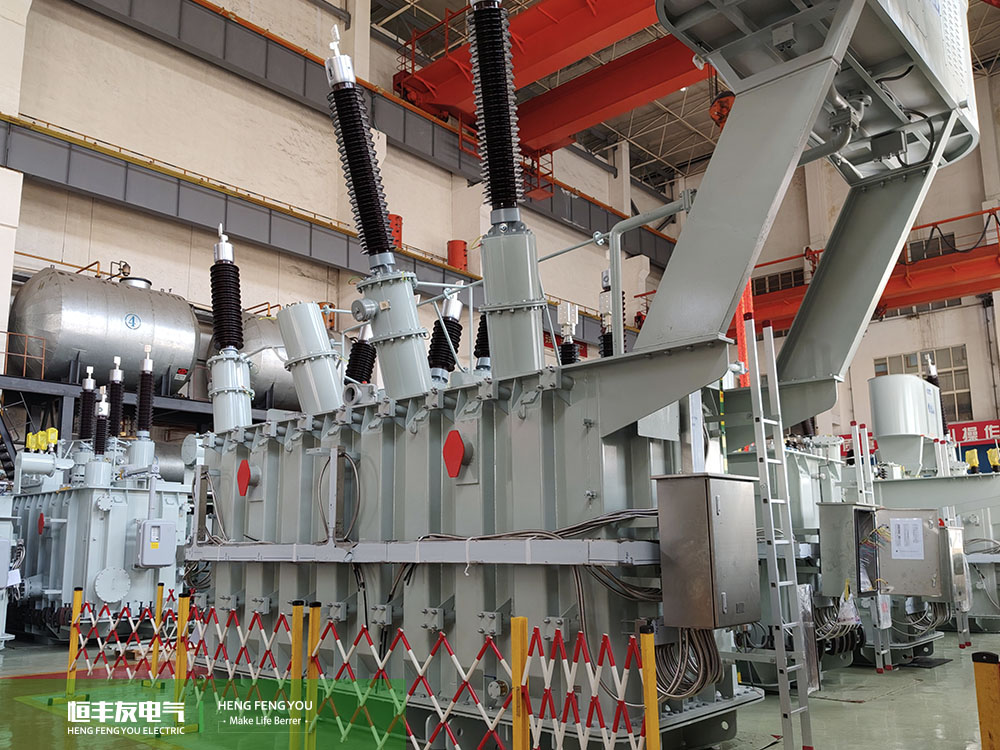
Insulation level is a separate design parameter from rated voltage and is frequently omitted from transformer specifications.
The windings must withstand the lightning impulse and power-frequency test voltages applicable to the connected system. For a 33 kV winding, a typical insulation specification may include a 170 kV lightning impulse withstand voltage and a 70 kV power-frequency withstand voltage.
These values must be verified against the applicable standard, system highest voltage, and utility requirements.
For a transformer connected directly to an overhead line or installed in an area with frequent lightning, insulation coordination is particularly important. For an indoor transformer connected through cables, the required insulation level may differ depending on the system design.
Use the utility's requirements rather than copying values from a generic reference table.
The vector group determines the phase relationship between the primary and secondary windings. It also affects the paths available for zero-sequence currents and influences the transformer's response to unbalanced loads and certain harmonics.
It is a mandatory compatibility requirement when transformers are intended to operate in parallel.
For a distribution transformer supplying a four-wire low-voltage network, Dyn11 is a common choice. Two transformers with incompatible vector groups cannot be operated in parallel simply because their other ratings are similar.
Changing the operating frequency changes the magnetic design requirements. A transformer designed for one frequency cannot automatically be assumed suitable for another.
When a transformer designed for 50 Hz operates at 60 Hz at the same voltage, its core flux density decreases. This generally reduces the risk of saturation and can improve the thermal margin.
The reverse is not necessarily true. Applying a 50 Hz voltage to a transformer designed exclusively for 60 Hz can increase core flux density enough to cause saturation, excessive excitation current, and overheating.
For 60 Hz projects, the core steel specification deserves particular attention. High-permeability grain-oriented electrical steel, including Hi-B grades, is a common choice for improving magnetic performance and reducing losses.
A design that meets a loss target on paper may have little margin once manufacturing variation is considered. Loss figures must also be compared at the same frequency and under equivalent test conditions. A 50 Hz loss figure cannot be directly compared with a 60 Hz specification as if the two represented identical conditions.
If future operation at another frequency is possible, state this requirement during the quotation stage. Dual-frequency operation can be incorporated into the original design, but it cannot necessarily be achieved by modifying a completed transformer.
Two projects with the same maximum demand may require different transformers because the characteristics of their loads differ.
Impact loads
Electric arc furnaces, rolling mills, and welding equipment can subject transformer windings and tap changers to repeated thermal and electrical stress. These applications require an assessment of cyclic loading and thermal effects rather than a steady-state temperature-rise check alone. Higher impedance may also be appropriate to limit current fluctuations, subject to voltage-drop and process requirements.
Nonlinear loads
Nonlinear loads inject harmonic currents into the electrical system. These currents can increase winding eddy-current losses and cause localized overheating, even when the overall RMS current appears acceptable.
Typical examples include rectifiers, variable-frequency drives, data center IT loads, and photovoltaic inverters. Where harmonic distortion is significant, provide the harmonic spectrum so that the transformer can be designed for the actual electrical conditions.
Frequently starting motors
Large motors with frequent starts create voltage dips and impose constraints on the transformer's impedance. The design must balance starting performance, voltage regulation, and short-circuit current.
Unbalanced single-phase loads
A three-phase transformer supplying substantial single-phase loads may experience phase-current imbalance. Depending on the winding configuration and grounding arrangement, a delta winding can provide a path for certain circulating and zero-sequence-related currents.
Solar and wind projects deserve separate consideration because their electrical characteristics differ from those of conventional motor loads.
Their loads and sources are interfaced through inverters. The resulting harmonic spectrum, reactive-power behavior, and operating profile depend on inverter design, grid conditions, and applicable grid codes.
Transformer selection should therefore be based on inverter output voltage, collector-system design, reactive-power requirements, harmonic characteristics, and grid-connection requirements.
Applying a conventional motor-load model directly to a renewable-energy project can lead to an inappropriate impedance selection.
Percentage short-circuit impedance is one of the most important parameters linking the transformer, switchgear, and protection system. Yet it is often copied from an earlier project without being checked against the new design.
Its primary function is to limit short-circuit current.
For a transformer with rated apparent power (S) in MVA, secondary voltage (U) in kV, and short-circuit impedance (u_k) expressed as a per-unit value, the approximate three-phase short-circuit current at the secondary terminals is:
[
I_{sc} \approx \frac{S}{\sqrt{3}\times U\times u_k}
]
This approximation assumes that the upstream system impedance is negligible. A complete fault study must also consider the upstream network and other relevant impedances.
Consider a 20 MVA, 11 kV transformer:
| Rated Capacity | Voltage | Short-Circuit Impedance (u_k) | Estimated Secondary Short-Circuit Current |
|---|---|---|---|
| 20 MVA | 11 kV | 6% | 17.5 kA |
| 20 MVA | 11 kV | 8% | 13.1 kA |
| 20 MVA | 11 kV | 10% | 10.5 kA |
Increasing impedance from 6% to 8% reduces the estimated short-circuit current from 17.5 kA to 13.1 kA.
If the switchgear has a short-circuit breaking rating of 16 kA, the difference can determine whether the proposed configuration is adequate. This is why transformer impedance cannot simply be copied from one project to another. If the switchgear changes, the impedance must be reviewed accordingly.
Higher impedance, however, comes with a trade-off: greater voltage drop under load.
A transformer with 10% impedance generally has a greater voltage drop than one with 6% impedance. On a long feeder, this drop adds to the voltage drop across the cables and other downstream equipment.
Typical impedance ranges vary by design and application. Distribution transformers commonly have impedance values in the range of 4%–6%, while larger power transformers may have values around 10%–14%. The final value must be determined from the system fault level, voltage-regulation requirements, and equipment ratings.
When two or more transformers operate in parallel, their key compatibility requirements include:
The same vector group and compatible phase displacement.
The same voltage ratio.
Corresponding tap positions.
Compatible percentage impedances and impedance angles.
Suitable rated capacities and load-sharing characteristics.
An impedance difference of approximately 10% or less is sometimes used as a preliminary guideline, but acceptable differences depend on the transformer ratings, impedance angles, and required load sharing. The design must be checked rather than relying on a single tolerance rule.
If the voltage ratios or tap positions are incompatible, circulating currents may occur even when the transformers are not supplying an external load.
Transformer impedance is subject to manufacturing tolerances. IEC 60076-1 specifies permitted deviations from declared values under defined conditions.
For certain transformer ratings and designs, the permitted impedance deviation may be ±10%, subject to the applicable requirements and any contractual guarantees. The exact tolerance must be verified for the specific transformer.
If the switchgear rating has no margin for impedance variation, the project may face a problem that could have been avoided during design.
Where short-circuit performance is critical, specify the required impedance and any tighter contractual tolerance clearly in the RFQ.
Cooling designations under IEC 60076 identify the internal cooling medium and the external cooling medium, with additional letters indicating forced circulation where applicable.
Common designations include:
ONAN: Oil Natural, Air Natural.
ONAF: Oil Natural, Air Forced.
OFAF: Oil Forced, Air Forced.
The cooling arrangement affects the rated capacity that can be assigned to a transformer with a given active part.
For example, a transformer rated at 10 MVA under ONAN cooling may be designed for 12.5 MVA under ONAF cooling. The actual ratings depend on the design and must be confirmed by the manufacturer.
The additional capacity comes with trade-offs, including fans, auxiliary power consumption, noise, maintenance, and additional failure modes.
If the fans fail, the transformer may have to return to its lower ONAN rating. If the load remains above that rating, the operator may need to reduce the load or risk excessive winding temperatures.
The specification must therefore state whether the required capacity applies with the fans operating or with natural cooling alone.
If short-duration peaks exceed the maximum continuous rating, specify whether additional forced-oil cooling or a defined short-term loading capability is required, including the permitted duration and operating conditions.
Noise is part of the same decision. Fan operation generally increases the overall noise level, so the sound power level under ONAN cooling does not necessarily represent the level under ONAF cooling.
For installations near property boundaries or residential areas, noise limits may become a planning constraint rather than merely a comfort consideration.
Two transformers that both comply with the specification can have significantly different lifetime costs. The purchase price alone does not account for the cost of energy losses.
A common approach is to capitalize transformer losses by assigning a monetary value to each watt of no-load loss and load loss.
Let:
(P_0) = no-load loss in watts.
(P_k) = load loss in watts.
(A) = capitalization factor for each watt of no-load loss.
(B) = capitalization factor for each watt of load loss.
The evaluated cost is:
[
\text{Evaluated Cost}=\text{Purchase Price}+A\times P_0+B\times P_k
]
The factors (A) and (B) depend on electricity prices, expected loading, operating hours, and the buyer's discount rate and evaluation methodology.
Consider two compliant quotations for a 2,000 kVA, 50 Hz distribution transformer:
| Item | Option A | Option B |
|---|---|---|
| Purchase Price (USD) | 42,000 | 49,000 |
| No-Load Loss (P_0) (W) | 2,100 | 1,500 |
| Load Loss (P_k) (W) | 18,000 | 15,000 |
| Evaluated Cost: (A=6.0,\ B=1.5) | 81,600 | 80,500 |
| Evaluated Cost: (A=3.0,\ B=0.75) | 61,500 | 64,750 |
Under the first set of capitalization factors, Option B costs USD 7,000 more upfront but has a USD 1,100 lower evaluated cost.
Under the second set of factors, Option A has a USD 3,250 lower evaluated cost.
The same two transformers can therefore produce different purchasing decisions under different evaluation assumptions. The factors belong to the buyer's evaluation methodology. Include them in the RFQ, or at least define the method that will be used to evaluate losses.
Otherwise, the buyer risks comparing purchase prices with evaluated costs, which are not the same thing.
Loss figures stated in a specification are not automatically equivalent to guaranteed test values.
IEC 60076-1 permits specified tolerances on measured losses under defined conditions. Depending on the applicable requirements, the tolerances can include +15% for no-load loss, +15% for load loss, and +10% for total loss.
A transformer may therefore meet the applicable standard while its measured losses exceed the declared values within the permitted tolerance.
If the project requires guaranteed loss values, state this explicitly in the specification and contract. Any tighter guarantee should be agreed with the manufacturer because it may affect the design, price, and available manufacturing margin.
Transformer ratings are based on specified environmental conditions. Common IEC reference conditions include a maximum ambient temperature of 40°C, a daily average of 30°C, and an annual average of 20°C.
If site conditions exceed the applicable reference conditions, the design and rating may need to be adjusted. This can be relevant in parts of the Middle East, Africa, and northern Australia.
Simply adding fans does not automatically resolve the issue. Permissible winding temperature rise and insulation limits must be evaluated against the actual ambient conditions.
Altitude also affects transformer design.
Above 1,000 m, reduced air density can affect external insulation performance and cooling. The required insulation clearances, dielectric performance, and temperature-rise limits should be checked against the applicable standards and project requirements.
At elevations above 2,000 m, altitude should be treated as an explicit design input rather than a minor note on the specification.
For outdoor transformers, bushing creepage distance must suit the site's pollution severity.
Specific creepage distance is commonly expressed in millimeters per kilovolt, based on the applicable voltage definition and insulation standard.
Coastal areas, cement plants, and dusty desert environments may require special consideration because of salt contamination, industrial deposits, or windblown dust.
This is primarily an external-insulation and bushing-selection issue, not a tank-design issue.
Transportation is often the last constraint to receive attention, yet it can cause significant project delays.
Large oil-immersed transformers may exceed standard road weight or dimensional limits, requiring low-bed trailers, special permits, route surveys, or bridge-load assessments.
Before the design is finalized, confirm:
Overall transport dimensions.
Total shipping weight.
Oil weight and shipping configuration.
Weight with the oil removed, where relevant.
Road, bridge, and route restrictions.
Any lifting, loading, and unloading constraints.
These details should be confirmed before design freeze, not after manufacturing has started.
The reference standards must be aligned before supplier quotations can be compared fairly.
IEC 60076 is widely used as the basis for international power transformer projects. GB/T 6451 is relevant to projects following applicable Chinese national requirements, while IEEE C57 standards are commonly used in North America and in projects elsewhere that specify them.
These standards are not interchangeable in every detail. Requirements for losses, tolerances, test procedures, and acceptance criteria can differ.
A transformer compliant with one standard may not satisfy another standard or a project's additional requirements.
Project-specific requirements may include:
Energy-efficiency regulations
The destination market may impose minimum energy-efficiency requirements or maximum permitted losses beyond the basic technical specification.
Utility specifications
The local utility may have its own technical requirements, approved-vendor lists, and documentation procedures.
Testing scope
Clarify whether the contract requires routine tests only or also type tests and special tests. Temperature-rise tests, lightning impulse tests, and short-circuit tests should be addressed explicitly where relevant, including whether customer or third-party witnessing is required.
Documentation and acceptance
Confirm the required document language, drawing approval schedule, inspection arrangements, and site acceptance criteria.
When any of these requirements remain unclear, asking the question before quotation is less costly than making assumptions that later require design changes.
1. Specifying kVA without providing the load profile or power factor.
Two transformers with the same rated capacity may not be suitable for the same operating conditions.
2. Copying impedance from a previous project.
The impedance must be checked against the current system fault level and switchgear ratings.
3. Comparing purchase prices alone.
Packaging, testing, transportation, spare parts, documentation, and payment terms can materially affect the overall project cost.
4. Treating specified losses as guaranteed losses.
Permitted standard tolerances may allow measured losses to exceed declared values unless tighter guarantees are agreed.
5. Applying a 60 Hz design directly to a 50 Hz system.
A transformer designed exclusively for 60 Hz may experience core saturation when energized at 50 Hz at the same voltage.
6. Leaving altitude and ambient-temperature corrections until design review.
By that stage, the thermal design may already have been completed using default conditions.
7. Over-specifying the transformer.
An unnecessarily high insulation level or enclosure protection rating can increase cost without delivering a corresponding reliability benefit. Requirements should reflect the actual installation and applicable standards.
At a minimum, provide the rated capacity in kVA or MVA, primary and secondary voltages, frequency, number of phases, vector group, tap range, cooling method, applicable standards, and installation conditions.
Also specify the required short-circuit impedance when it affects switchgear selection, loss requirements when losses will be evaluated, and the destination port or delivery location.
The more complete the technical information, the fewer clarification rounds are needed before a technically comparable quotation can be prepared.
Not necessarily. The decision depends on the loss capitalization factors, expected loading, operating hours, electricity prices, and the evaluation period.
A transformer operating at a consistently low load may incur a large proportion of its lifetime loss cost through no-load losses. In this case, reducing (P_0) may be more valuable than reducing (P_k).
Use the evaluated-cost method described in Section 7 rather than comparing efficiency figures or purchase prices in isolation.
Yes, within the applicable thermal and operating limits.
The permissible overload depends on the load before the overload, ambient temperature, cooling conditions, and the duration of the overload. It must be assessed for the specific transformer rather than assumed to be a fixed percentage.
Rated capacity is the output a transformer can supply continuously under its specified operating conditions without exceeding the applicable temperature-rise limits.
Actual load is the power demanded by the connected system at a particular moment. It varies throughout the day and across the year.
Sizing only for the peak can result in excessive unused capacity, while sizing only for average demand may leave insufficient capacity during peaks and increase thermal stress. Demand and diversity factors help account for these variations, but the final selection must reflect the actual load profile and expected future demand.
Lead time depends on the transformer's capacity, whether it is a standard distribution transformer or a specially designed power transformer, material availability—particularly electrical steel and copper—and the manufacturer's production schedule.
The process typically includes design and drawing approval, material procurement, core and winding manufacture, vacuum drying, final assembly, testing, and packaging.
A delivery commitment made before the technical scope is finalized is not a reliable schedule. At Hengfengyou Electric, we first confirm your required delivery date and technical specifications, then assess the production schedule and determine whether the target can be met.
Oil-Immersed Distribution Transformers
Power Transformers
Cast Resin Dry-Type Transformers
Compact Substations
Medium-Voltage Switchgear
Transmission Towers
Power Cables
Renewable Energy Electrical Equipment
Internal-link anchor text should be updated to match the final product names and URLs on the official website.
Solar Power Plant Electrical Solutions
Mining Power Distribution Solutions
Industrial and Grid Substation Solutions
Internal-link anchor text should be updated to match the final industry solution page names and URLs.
If your technical specification is ready, send it to us and we will review the requirements and prepare a quotation.
If you only have the required capacity and voltage ratio, that is a useful starting point. Share those details with us, and we can work through the remaining technical considerations together before finalizing the proposed solution.
Qingdao Hengfengyou Electrical Engineering Co., Ltd.
Contact: Michael Zhong
Electrical Engineer, Global Solutions Department
Mobile / WhatsApp / WeChat: +86 191 7903 1830
Email: michael@hengfengyou.com
Tel: +86-532-87936206
Website: www.hengfengyou.com
Address: No. 638, Zhongcheng Road, Chengyang District, Qingdao, Shandong, China
WhatsApp:
+86 13969788801
+86 15853252696
Tel:+86-0532-68688801
Fax:+86-0532-87038801
Email: hfy@hengfengyou.com
Address: No.638,Zhongcheng Road, Chengyang District, Qingdao City,China
Leave a message now - get the latest industry insights, star products, and success stories of hengfengyou electric