What protection does the main transformer have? Selection principle of main transformer?
Writer: Hengfeng you electric Time:2023-04-06 views:times
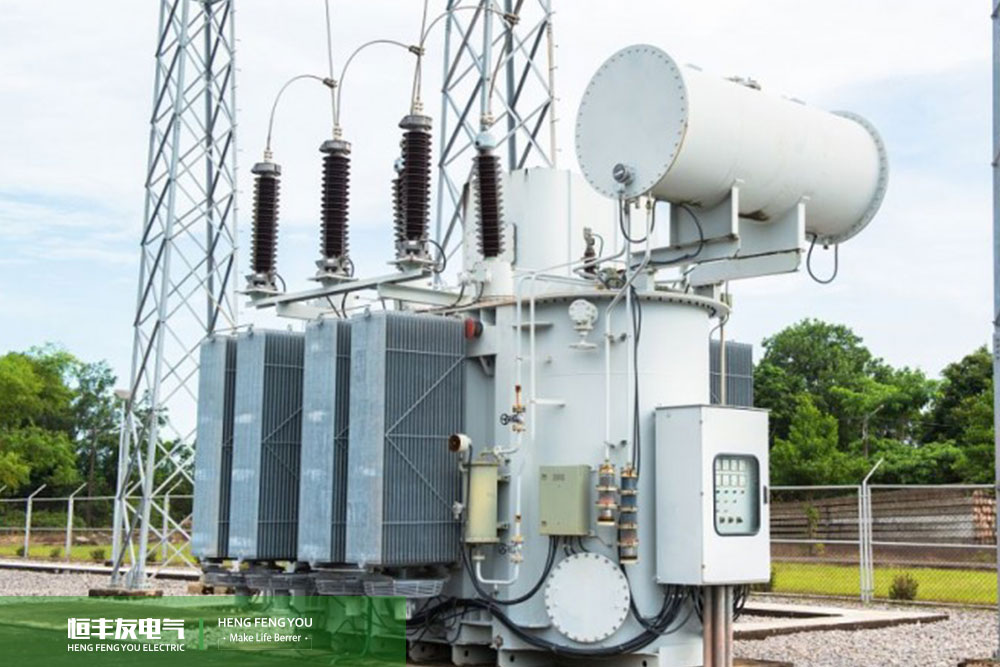
differential protection of main transformer: the differential protection can reflect all kinds of inter phase, grounding and inter turn short-circuit faults in the transformer, and can also reflect the short-circuit fault of outgoing line bushing.
What protection does the main transformer have
(1) Main transformer differential protection: the differential protection can reflect all kinds of inter phase, grounding and inter turn short-circuit faults in the transformer, and can also reflect the short-circuit fault of outgoing line bushing.
(2) Gas protection: gas protection can reflect internal burning loss of iron core, internal short circuit and disconnection of winding, gradual aging of insulation, decline of oil level and other faults, but cannot reflect faults outside the transformer body.
(3) Zero sequence current protection: zero sequence current protection can reflect the grounding short-circuit fault inside or outside the transformer. Generally, the complete zero sequence current protection is composed of zero sequence current, gap zero sequence current and zero sequence voltage.
(4) Overload protection: the overload protection reflects the overload state of the transformer.
(5) Phase to phase protection: the phase to phase backup protection of the transformer is similar to that of the generator.
(6) Input protection: input protection includes winding temperature protection, oil level protection, ventilation fault protection, cooler fault protection, pressure release, etc., as well as reflecting some abnormalities such as temperature, oil level and ventilation.
(7) Longitudinal differential protection of generator transformer unit: the longitudinal differential protection of generator transformer unit is also realized by the relay with ratio and harmonic braking characteristics. The generator transformer longitudinal differential protection usually adopts three side current differential, and the input current is taken from the current transformer at the neutral point of the generator, the current transformer at the high voltage side of the auxiliary transformer and the current transformer at the circuit breaker at the high voltage side of the main transformer.
What protection does the main transformer have? Selection principle of main transformer?
Selection principle of main transformer
1. Determination of transformer quantity
(1) The principle of determining the number of main transformers is to ensure the reliability of power supply. When one of the following conditions is met, two or more transformers should be installed.
① When there are a large number of first-class loads and they are second-class loads but need to be set for security (such as fire fighting).
② When seasonal load changes greatly.
③ When the concentrated load is large.
For large hub substations, 2-4 main transformers can be installed according to the specific conditions of the project.
When multiple transformers are installed, they should be properly grouped according to the load characteristics and changes so as to flexibly switch the corresponding transformer groups. Transformers shall be operated in a split mode. The neutral wire and neutral grounding wire at the low-voltage outgoing end of the transformer shall be laid separately. In order to facilitate the test, a detachable connection device is made near the transformer in the grounding circuit.
(2) Generally, class III load or power and lighting with small capacity should share the same load and only use one transformer.
① When the lighting load is large or the common transformer used for power and lighting seriously affects the lighting quality and bulb life, a special transformer for lighting can be set.
② When single single-phase load is large, single-phase transformer should be set.
③ When the impact load is large and the power quality is seriously affected, a special transformer for impact load can be set.
④ When seasonal loads (such as air conditioning equipment) account for 1 / 3 or more of the total power load of the project, special transformers should be provided.
2. Determination of structural type
(1) The building requires a substation in a multi-storey or high-rise main building. The transformer can generally be epoxy resin cast copper core winding dry-type transformer and equipped with temperature monitoring and alarm devices. In places where dust or corrosive gas seriously affects the safe operation of transformers, dust-proof or anti-corrosion transformers shall be selected. Immersion insulation dry-type transformer should not be set in particularly humid environment.
For the three-phase transformer set on the second floor or above, the influence of vertical and horizontal transportation on the load of the channel and floor shall be considered. If the dry-type transformer is used, its capacity shall not be greater than 630kVA. The capacity of a single transformer in the substation of the residential area should not be greater than 630kVA.
(2) The combustible oil immersed power transformer shall be installed in a separate room. Detachable guardrails should be installed on both sides of the transformer high-voltage side Bay.
The transformer and the low-voltage distribution room as well as the transformer room shall be provided with channel solid doors. If wooden doors are used, iron sheets shall be wrapped on one side of the transformer. The transformer base shall be provided with anti vibration measures such as fixed fixtures. The noise level of the transformer shall be strictly controlled. If necessary, measures such as adding noise reduction pads can be taken to meet the national environmental noise hygiene standards. The noise level in the relevant living and working rooms shall be ≤ 45dB (a) during the day and ≤ 35dB (a) at night.
The high-voltage distribution cabinet adopts the wiring mode of bottom in and bottom out, and the cable interlayer is set under the high-voltage distribution room. The low-voltage distribution cabinet adopts the wiring mode of top in and top out, and the cable tray is arranged above the cabinet top for wiring. There are advantages and disadvantages of the upper in and upper out and the lower in and lower out wiring methods: the upper in and upper out can be saved as the structural layer, but it requires a cable tray, and the installation requirements are extremely strict. The connection method of bottom in and bottom out must be a structural layer, and no cable tray is required. The high and low voltage distribution rooms shall be equipped with gas fire extinguishing and exhaust systems.
For the indoor oil immersed transformer under on-site maintenance, the indoor height can be increased by 0.7m according to the minimum height required for core hanging; The width can be determined by adding 0.8m on both sides of the transformer. When multiple dry-type transformers are arranged in the same room, the clear distance between the transformer protection enclosures shall not be less than the safe distance.
(3) Voltage regulation when the user system has voltage regulation requirements, the on load automatic voltage regulation power transformer shall be selected. For the newly-built power substation, it is suggested to adopt on load automatic voltage regulation transformer, which is beneficial to the economy of network operation. Although the temporary investment is slightly higher, the additional investment can be recovered in a short time.
When a substation with three voltages is required, and the power passing through the coils on each side of the main transformer reaches more than 15% of the capacity of the transformer, the main transformer should adopt a three coil transformer. Such as 220kV, 110kV and 35kV, three winding transformer is usually used.
(4) Special transformer can be set in case of the following conditions: when the common transformer is used for power and lighting, which seriously affects the lighting quality and bulb life, special transformer can be set. When the seasonal load capacity is large (such as the load of air conditioners and freezers in large civil buildings), special transformers can be set. For the transformer with y, YNO connection, when the neutral line current caused by single-phase unbalanced load exceeds 25% of the rated current of the low-voltage winding of the transformer, a single-phase transformer should be set. Special transformers should be set for some special equipment (such as X-ray machine with large capacity, etc.) for functional needs.
(5) When the single-phase short-circuit current value needs to be increased or the third harmonic content needs to be limited, or the three-phase unbalanced load exceeds 15% of the rated capacity of each phase of the transformer, the D, yn11 type transformer should be selected.
(6) Since the live part of the IT system is not directly connected to the ground, the lighting cannot share the transformer with the power, and a special lighting transformer must be set.
3. Selection of distribution transformer capacity
(1) General principles for capacity selection of transformers
The transformer capacity shall be selected according to the calculated load. When determining the capacity of a transformer, the load rate of the transformer shall be determined first. When the no-load loss of the transformer is equal to the square of the load rate multiplied by the load loss, the efficiency is the highest. The load rate of the transformer at the highest point of efficiency is between 63% and 67%. For a single transformer with stable load supply, the load rate is generally about 85%. However, this is only a conclusion drawn from the perspective of power saving, which is not comprehensive enough. Other important elements worth considering are various economic costs of operating the transformer, including fixed asset investment, annual operation cost, depreciation cost, tax, insurance cost and some other expenses. When selecting the transformer capacity, it is only a choice to appropriately increase the load rate of the transformer to reduce the number or capacity of the transformer, that is, to sacrifice the operation efficiency and reduce the primary investment.
(2) When two or more main transformers are installed, the capacity of each transformer shall be selected in such a way that when any one of them is shut down, the remaining capacity can at least guarantee the first-class load supplied or 60-75% of the total load of the substation. Generally, 75% is adopted for the primary substation and 60% is adopted for the secondary substation.
The power factor of the primary side of the transformer is related to the load rate. The power factor of the primary side is 3-5% lower than that of the secondary side during full load operation. When the load rate is less than 60%, the power factor of the primary side is 11% - 18% lower than that of the secondary side. High load rate is favorable for improving power factor at high voltage side. The load rate is high, the capacity of the circuit breaker is large, and the investment will be increased.
(3) The capacity of a single transformer in the low-voltage 0.4kV substation should not be greater than 1600KVA. When the capacity of the electrical equipment is large, the load is concentrated and the operation is reasonable, the transformer with the capacity of 2000kVA and above can be selected. In recent years, some manufacturers have been able to produce me and ah type low-voltage circuit breakers and current limiting low-voltage circuit breakers with large capacity. In civil buildings, more transformers of 1250kva and 1600KVA are used, especially 1250kva. Therefore, it is recommended that the single capacity of transformer should not be greater than 1250kva.
When the dry-type transformer is adopted, the winding thermal protection device shall be equipped. Its main functions shall include: temperature sensor disconnection alarm, fan start / stop, over temperature alarm / trip, three-phase winding temperature patrol detection maximum value display, etc.
The energy-saving transformer shall be selected. The overload capacity of the transformer shall be considered for the overload in case of accident. If necessary, forced air cooling measures can be taken. When the single-phase short-circuit current value needs to be increased or the third harmonic content needs to be limited, or the three-phase unbalanced load exceeds 15% of the rated capacity of each phase of the transformer, the D, yn11 type transformer should be selected.
The non combustible oil transformer can be installed in an independent room or near the low-voltage side power distribution device, but measures shall be taken to prevent personal contact. The non fuel oil transformer shall have a protection enclosure grade not lower than IP2X. The indoor combustible oil immersed power transformer shall be installed in a separate room. Detachable guardrails should be installed on both sides of the transformer high-voltage side (including the lead-in cable) interval.
The transformer and the low-voltage distribution room as well as the transformer room shall be provided with channel solid doors. If wooden doors are used, iron sheets shall be wrapped on one side of the transformer. The transformer base shall be provided with anti vibration measures such as fixed fixtures. The noise level of the transformer shall be strictly controlled. If necessary, measures such as adding noise reduction pads can be taken to meet the national environmental noise hygiene standards (in the relevant living and working rooms). The noise level shall be ≤ 45dB (a) during the day and ≤ 35dB (a) at night.
Three phase protection shall be adopted for overcurrent protection of transformer. When the fuse is used as the transformer protection at the high-voltage side, the melt current shall be 1.4-2 times of the rated current of the transformer. The main switch and bus breaker on the low-voltage side of the transformer shall be selective. The low-voltage side busbar of the power transformation and distribution room shall be equipped with a low-voltage lightning arrester. The capacity of a single transformer should not be greater than 1600KVA. When the capacity of the electrical equipment is large, the load is concentrated and the operation is reasonable, the transformer with the capacity of 2000kVA and above can be selected. When the dry-type transformer is adopted, the winding thermal protection device shall be equipped. Its main functions shall include: temperature sensor disconnection alarm, fan start / stop, over temperature alarm / trip, three-phase winding temperature patrol detection maximum value display, etc.
(4) Determination of transformer capacity
① Factor of impulse current: the peak current of single motor, arc welding or welding transformer branch is
Ijf=KIN(A)
Where, in - rated current of high voltage side of motor, arc welding machine or welding transformer.
K - multiple of starting current, i.e. the ratio of starting current to rated current.
② For the distribution line connected with multiple motors, only the peak current when one motor is started shall be considered:
Ijf=(KIN)max+Ifs(A)
Where (kin) max - starting current of the motor with the largest starting current when starting.
Ifs - calculated current of the distribution line excluding the starting motor.
③ For self starting motor group, its peak current is the sum of all motor currents participating in starting.
4. Parallel operation
When there are two or more transformers operating at the same time in the substation, the following conditions must be met
(1) The primary and secondary rated voltages of each transformer must be equal. For example, the primary high voltage is 10kV and the low voltage is 0.4kV. The error shall not be greater than ± 5%. If the transformation ratio of two transformers is different, the circulating current will be generated in the secondary winding, which is easy to cause the transformer to overheat and burn.
(2) The short-circuit voltage of each transformer in parallel must be equal. Short circuit voltage is also called impedance voltage. Since the load of parallel running transformers is inversely distributed according to the impedance voltage value, the transformer with small impedance voltage will be damaged due to the high distributed voltage. Generally, the allowable difference is not more than ± 10%.
(3) The connection groups of parallel connected transformers must be the same. That is to say, the phase sequence of the primary or secondary voltage of each transformer must correspond to each other, otherwise it cannot operate in parallel. For example, when two transformers connected with D, yn11 and y, YNO are connected in parallel, a phase difference of 30 ° will appear on their corresponding secondary side, resulting in a potential difference between the secondary windings Δ Thereby generating a large circulation.
(4) The rated capacity of each transformer in parallel shall be as similar as possible, and the ratio of capacity shall not exceed 1:3. This is mainly because the capacity difference of the transformer is too large and the circulating current will be generated due to different internal impedance or other characteristics, which will affect the service life of the transformer.
For more information, please pay attention to Qingdao hengfengyou electric. Our factory focuses on the production and manufacturing of American box type substation, which has been sold to the American market in 2018.
American pad transformer, American transformer, pad mounted transformer customized production. Thirty years of production experience in the global power market.. Hengfengyou Electric will provide you with the best American pad transformer product solution. Hengfengyou electric provides you with the best electrical product solutions. 【WhatsApp:+86158 5325 2696(Jack) +86158 5326 5269(Alisa) info@hengfengyou.com https://www.hengfengyou.com 】