HENGFENGYOU ELECTRIC --SMART ELECTRIC GLOBAL SERVICE PROVIDER



Writer: Hengfeng you electric Time:2026-08-07 views:times
For industrial applications, the 10kV/0.4kV three‑phase oil‑immersed industrial distribution transformer is the mainstream choice. For heavy‑load workshops with large‑capacity loads and outdoor plant sites, ONAN oil‑immersed natural cooling and ONAF oil‑immersed forced‑air cooling types are preferred. Dry‑type industrial distribution transformers are adopted for basements, precision‑processing workshops and power distribution rooms in high‑rise buildings where fire‑protection requirements are stringent.
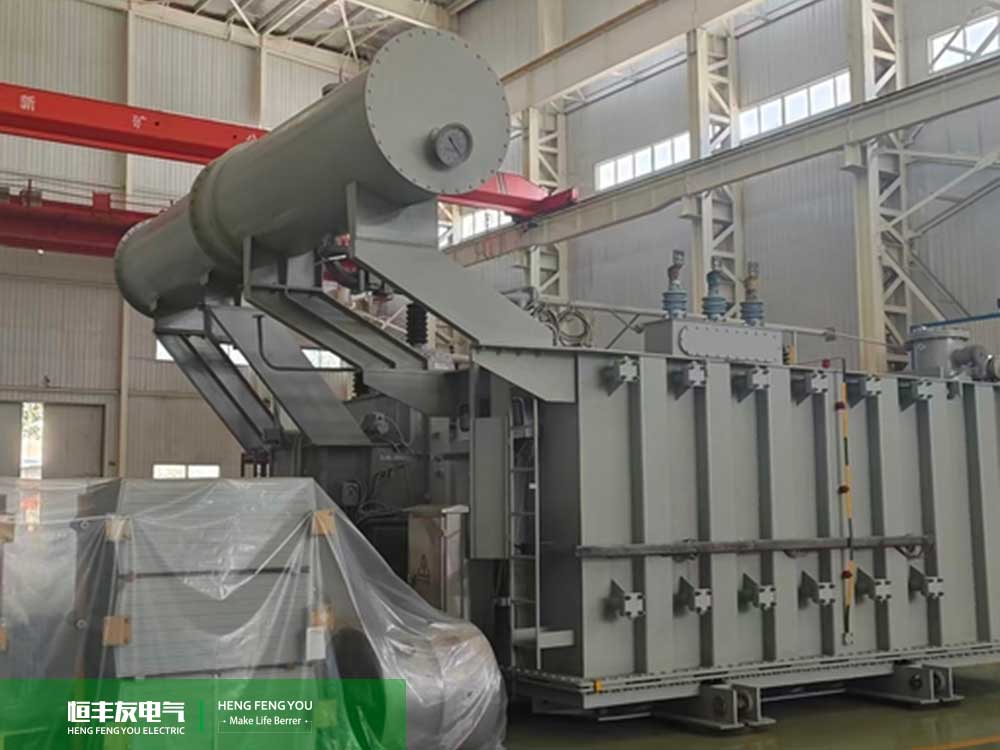
Core components of industrial distribution transformers include iron cores, high‑ and low‑voltage windings, insulating oil (for oil‑immersed units), oil‑tank heat‑dissipation systems, tap‑changers, high‑ and low‑voltage bushings, and temperature‑control protection devices. By electromagnetic induction, step‑down conversion from 10 kV high‑voltage side to 0.4 kV low‑voltage side is realised to supply power for industrial loads such as motors, frequency converters, production lines and air compressors.
Different from civil distribution transformers, industrial distribution transformers must withstand motor‑starting surges, cyclic heavy loads and short‑term overloads. Therefore, stricter criteria apply to the selection of capacity, impedance and loss grades.
Rated capacity, measured in kVA, is the primary core parameter for transformer selection. It cannot be simply calculated by summing the power of existing equipment. Three factors shall be incorporated: diversity factor, expansion margin and starting impulse load.
Transformer calculated load: S = P ÷ (cosφ × K) ‑ P: Total rated active power of all power‑consuming equipment on‑site (kW) ‑ cosφ: Comprehensive power factor of industrial plants, generally 0.8‑0.85; up to 0.95 with reactive‑power compensation installed ‑ K: Load diversity factor: 0.6‑0.7 for small‑scale processing plants; 0.8‑0.9 for large continuous‑production workshops
1. No capacity expansion planned within 3 years: reserve 10%‑20% margin 2. New production lines, energy‑storage facilities or high‑power equipment planned: reserve 30%‑40% margin
Direct starting of a single high‑power motor (≥ 55 kW) generates impulse current 5‑7 times the rated value. Insufficient transformer capacity will lead to sharp voltage drop upon motor start‑up and equipment malfunction.
Selection experience: The power of the largest single motor should not exceed 30% of the transformer rated capacity. Otherwise, upgrade the transformer capacity by one grade or adopt soft‑start / variable‑frequency start‑up modes.
Common industrial ratings: 315 kVA, 400 kVA, 500 kVA, 630 kVA, 800 kVA, 1000 kVA, 1250 kVA, 1600 kVA, 2000 kVA, 2500 kVA
Case: Capacity‑selection mistake and subsequent capacity‑expansion retrofit for a mechanical‑processing plant A small hardware‑processing plant had total equipment power of 320 kW. When purchasing, only existing loads were taken into account without reserving expansion margin, and a 400 kVA oil‑immersed industrial distribution transformer was selected. With a diversity factor of 0.7, the calculated load stood at merely 158 kVA, and the unit operated normally in the initial production phase.
One year after commissioning, two 75 kW CNC stamping machines were added, lifting the plant’s total power to 470 kW. During peak periods, the transformer load rate exceeded 110%, triggering frequent high‑temperature alarms, insufficient starting torque for production‑line motors and flickering lighting.
Re‑measurement and calculation by the technical department showed that the calculated load reached 246 kVA after adding new equipment. With a 30% expansion margin, 630 kVA was the reasonable capacity. The plant suspended production for 15 days for transformer replacement, incurring additional costs totalling over CNY 120 000 for equipment procurement, civil‑engineering work, switchgear modification and production‑halt losses.
Selection lesson: Industrial plants shall plan production capacity for 3‑5 years in advance and reserve at least 20% capacity margin. A 30% margin is required if new high‑power‑equipment installation is planned.
Short‑circuit impedance (Uk%) is a frequently overlooked critical parameter. It directly determines system short‑circuit current, busbar dynamic‑thermal stability and voltage‑fluctuation amplitude. Conventional impedance values for national‑standard oil‑immersed industrial distribution transformers are 4%, 6%, 8% and 10.5%.
Hunter, technical engineer at Hengfengyou Electric (hunter@hengfengyou.com), has long provided load‑calculation and complete‑set transformer solutions for mining, chemical and new‑energy plants. He reminds buyers not to choose low‑impedance models merely to cut procurement costs.
‑ Low impedance Uk = 4% (light‑duty small‑scale processing plants) Applicable to: Light‑duty processing plants with stable loads, few frequency converters and limited low‑voltage switchgear outgoing circuits Advantages: Minor voltage regulation deviation, stable operating voltage for equipment, lower transformer procurement cost Disadvantages: High short‑circuit current on the low‑voltage side; higher breaking‑capacity grades are required for switchgears and circuit breakers, raising overall costs of complete‑set equipment
‑ Medium impedance Uk = 6% (general‑purpose standard industrial plants) Applicable to: Most mechanical‑processing, hardware‑processing and food‑manufacturing plants. Balances voltage stability and short‑circuit‑current limiting. It is the mainstream commercial option with optimal cost‑performance.
‑ High impedance Uk = 8% / 10.5% (heavy‑duty plants with multiple frequency converters and new‑energy supporting facilities) Applicable to: Metallurgy, mining, chemical‑industry facilities, PV‑energy‑storage step‑up stations and workshops with numerous frequency converters Core functions: Limit low‑voltage‑side short‑circuit current, mitigate dynamic‑thermal stress on switchgears, copper busbars and cables, reduce failure‑caused burnout risks, and avoid system resonance triggered by multi‑harmonic equipment Disadvantages: Larger voltage drop under load fluctuation; reactive‑power‑compensation devices are required for voltage stabilisation
‑ Ordinary light‑duty plants: Prioritise 6%‑impedance industrial distribution transformers ‑ Workshops with multiple frequency converters, high‑power motors or flammable‑and‑hazardous chemical‑industry processes: Adopt industrial distribution transformers with impedance of 8% or above
Real‑world Case 3: Switchgear burnout caused by improper low‑impedance industrial‑distribution‑transformer selection in a chemical plant When procuring a 1600 kVA oil‑immersed industrial distribution transformer for a fine‑chemical‑production workshop, the plant blindly selected a Uk = 4% low‑impedance model to lower costs, paired with conventional low‑voltage complete‑set switchgears with 31.5 kA breaking capacity.
The workshop contained more than 20 frequency‑conversion stirring reactors and high‑power refrigeration compressors, resulting in high‑system‑harmonic content. Half a year after commissioning, phase‑to‑phase short‑circuit occurred due to insulation damage of low‑voltage outgoing cables. The low‑impedance transformer generated short‑circuit current far exceeding the rated breaking value of the switchgear. The incoming circuit breaker failed to extinguish arcs rapidly. Copper busbars in high‑voltage switchgears melted, and the whole section of power‑distribution busbars burned out. The whole plant suspended production for 7 days for maintenance, with direct economic losses exceeding CNY 280 000.
Rectification measures: Replace with a 1600 kVA first‑energy‑efficiency high‑impedance (Uk = 8%) industrial distribution transformer. Simultaneously replace with 40 kA high‑breaking‑capacity complete‑set switchgears and install active harmonic‑compensation devices to eliminate potential faults completely.
Transformer losses consist of no‑load loss (iron loss) and load loss (copper loss). The energy‑efficiency grade of industrial distribution transformers directly determines long‑term plant electricity expenses and constitutes a mandatory requirement for current environmental‑protection and energy‑saving acceptance.
1. No‑load loss: Continuous iron‑core loss when the transformer is energised under no‑load conditions. It exists 24 hours a day and exerts significant impact on continuously‑operating plants. 2. Load loss: Winding heating loss under loaded operation. Loss increases as the load rises.
‑ Grade 3: Outdated conventional type with high no‑load and load losses. Only suitable for short‑term power supply at temporary construction sites. Not recommended for newly‑built plants. ‑ Grade 2: Popular energy‑saving model with roughly 20% loss reduction. Standard configuration for small‑and‑medium‑sized plants, balancing procurement cost and energy‑saving performance. ‑ Grade 1: Ultra‑high‑efficiency oil‑immersed industrial distribution transformer with substantially reduced losses. Mandatorily recommended for plants operating 24 hours a day, government‑managed industrial parks and new‑energy projects. Aligns with dual‑carbon energy‑saving policies and qualifies for energy‑saving subsidies.
表格
| Energy‑efficiency Grade | Applicable Scenarios | Long‑term Power‑Consumption Cost | Procurement Cost | Policy Compliance |
|---|---|---|---|---|
| Grade 3 | Short‑term power supply for temporary construction sites | High | Lowest | Fails energy‑saving acceptance |
| Grade 2 | Two‑shift intermittent‑production plants | Medium | Moderate | General‑purpose for ordinary plants |
| Grade 1 | Chemical‑industry, PV and 24‑hour continuous‑production plants | Low | Slightly high | Eligible for energy‑saving subsidies |
1. Two‑shift intermittent‑production plants: Grade‑2‑energy‑efficiency industrial distribution transformers deliver optimal cost‑performance. 2. 24‑hour continuous‑production plants, chemical‑industry facilities, PV projects and large‑scale industrial parks: Grade‑1‑energy‑efficiency oil‑immersed industrial distribution transformers must be adopted. 3. Power‑distribution retrofits for ageing plants: Phase out Grade‑3‑energy‑efficiency transformers and replace with Grade‑1 or Grade‑2 energy‑saving models to cut monthly basic electricity charges.
Real‑world Case 4: Energy‑saving‑retrofit benefits for an old Grade‑3‑energy‑efficiency industrial distribution transformer at a hardware‑processing plant A three‑shift hardware‑stamping plant in Shandong operated an original 1000 kVA S11 Grade‑3‑energy‑efficiency oil‑immersed industrial distribution transformer, running 24 hours a day for 360 days per year, with industrial electricity price of CNY 0.8 per kWh. Before retrofit, monthly electricity charges for transformer no‑load plus load losses reached around CNY 3 800, with annual loss‑related electricity costs of CNY 45 600.
In 2025, the plant upgraded its power‑distribution system and replaced the unit with an S20 Grade‑1‑energy‑efficiency oil‑immersed industrial distribution transformer of equal capacity. After retrofit, monthly loss‑related electricity charges dropped to CNY 2 460, saving CNY 16 000 per year. The price difference for equipment procurement was CNY 80 000, and the retrofit investment can be recovered within 5 years. Over the 30‑year design service life of the transformer, cumulative power‑saving exceeds 480 000 kWh. Meanwhile, the plant passed local special‑purpose energy‑saving acceptance and obtained an energy‑saving subsidy of CNY 12 000.
1. Vector group symbol Where low‑voltage sides carry large volumes of single‑phase lighting and control equipment, Dyn11 is preferred. Yyn0 can be adopted for purely three‑phase dynamic loads. Dyn11 provides stronger third‑harmonic suppression and suits workshops with numerous frequency converters.
2. Cooling‑mode matching with capacity ‑ ≤ 1600 kVA: ONAN oil‑immersed natural cooling suffices ‑ ≥ 2000 kVA heavy‑duty industrial distribution transformers: Adopt ONAF oil‑immersed forced‑air cooling to improve overload capacity
3. Installation‑environment adaptability ‑ Outdoor plant sites without strict fire‑protection constraints: Oil‑immersed industrial distribution transformers ‑ Power‑distribution rooms, basements and precision‑processing workshops: Dry‑type energy‑saving industrial distribution transformers
1. Determine capacity merely according to existing‑equipment power without reserving expansion margin. Capacity‑expansion retrofit is required 1‑2 years after commissioning, bringing higher secondary‑construction costs (Hardware‑plant Case 1). 2. Blindly select 4% low‑impedance industrial distribution transformers. Excessive short‑circuit current occurs in workshops with multiple frequency converters, leading to frequent burnout of low‑voltage‑switchgear components (Chemical‑plant Case 3). 3. Choose Grade‑3 low‑efficiency transformers to cut procurement costs. Long‑term loss‑related electricity expenses far exceed equipment‑price differences, and energy‑saving acceptance cannot be passed (Hardware‑plant‑retrofit Case 4). 4. Fail to perform capacity correction for high‑power motors. Excessively low voltage occurs upon motor start‑up, preventing production lines from full‑load operation. 5. Adopt conventional 6%‑impedance transformers for new‑energy and multi‑harmonic‑load scenarios without matching harmonic‑mitigation equipment. Long‑term resonance accelerates winding ageing.
Procurement price shall not be the sole consideration for industrial‑distribution‑transformer selection. Rated capacity determines power‑supply carrying capacity; short‑circuit impedance guarantees safe operation of complete‑set electrical equipment; energy‑efficiency‑loss grade controls long‑term power‑consumption costs. These three parameters interact with one another.
For small‑and‑medium‑sized intermittent‑production plants, Grade‑2‑energy‑efficiency industrial distribution transformers with 6% standard impedance and 20% reserved capacity margin are recommended. For 24‑hour continuous‑production plants, new‑energy facilities and heavy‑duty chemical‑industry sites, Grade‑1‑energy‑efficiency high‑impedance industrial distribution transformers with over 30% reserved expansion space are suggested.
The entire selection process shall strictly follow national standards for power transformers including GB/T 6451, GB 20052 and GB/T 1094. Comprehensive evaluation shall be carried out in combination with plant production loads, equipment types and capacity planning, so as to avoid economic losses such as rework for capacity expansion, short‑circuit burnout and excessive energy consumption illustrated in practical cases.
Hengfengyou Electric is an export‑oriented enterprise specialising in the R&D and manufacturing of power transmission and distribution equipment. Its main products cover three‑phase oil‑immersed and dry‑type industrial distribution transformers, as well as high‑ and low‑voltage complete‑set switchgears. All product ranges comply with national Grade‑1 and Grade‑2 energy‑efficiency standards and hold complete 3C and energy‑efficiency test certifications. Its technical team can custom‑design industrial distribution transformers with optimised capacity, short‑circuit impedance and cooling modes according to plant load lists, and deliver integrated complete‑set power‑distribution solutions. The products are widely applied in mining, chemical, machinery manufacturing, photovoltaic new‑energy and municipal park projects, with deliveries across all provinces in China and more than ten countries worldwide.
If you require accurate load calculation, or complete power‑distribution solutions covering industrial distribution transformers, supporting switchgears and cables, please provide your plant equipment list to obtain professional technical selection advice and precise quotations.
Email: hunter@hengfengyou.com
WhatsApp/Mobile: +8618224429139
WhatsApp:
+86 13969788801
+86 15853252696
Tel:+86-0532-68688801
Fax:+86-0532-87038801
Email: hfy@hengfengyou.com
Address: No.638,Zhongcheng Road, Chengyang District, Qingdao City,China
Leave a message now - get the latest industry insights, star products, and success stories of hengfengyou electric