Key Points for Selecting GIS Gas-Insulated Switchgear: How to Determine Voltage Levels, Insulation Configuration, and Gas Compartment Structure?
Writer: Hengfeng you electric Time:2026-08-13 views:times
I. How Are GIS and C-GIS Gas-Insulated Switchgear Classified?
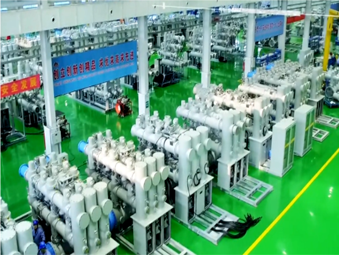
GIS (Gas Insulated Switchgear) is a high-voltage switchgear that uses a metal-enclosed structure and relies on insulating gas or gas mixtures to achieve partial or complete insulation functions. High-voltage GIS typically integrates functional units such as circuit breakers, disconnectors, earthing switches, busbars, current transformers, voltage transformers, surge arresters, and gas monitoring devices. Its compact modular design reduces equipment footprint and improves adaptability to the operating environment.
For metal-enclosed switchgear with a rated voltage above 1kV and up to 52kV, related products can be designed and tested according to IEC 62271-200. AC gas-insulated metal-enclosed switchgear with a rated voltage higher than 52kV corresponds to IEC 62271-203. Specific products also require complete technical design incorporating corresponding product standards for circuit breakers, disconnectors, instrument transformers, and other components.
C-GIS (Compact Gas Insulated Switchgear) is typically used for medium-voltage distribution scenarios. It features a compact structure, smaller footprint, and reduced susceptibility to external environmental influences. It can be applied in industrial plants, urban power distribution rooms, prefabricated cabins, data centers, commercial buildings, and new energy power distribution projects.
It is important to note that C-GIS is not synonymous with SF₆ switchgear. Different products may utilize SF₆, alternative gases, vacuum interrupters combined with gas insulation, or other composite insulation schemes. Therefore, when selecting a C-GIS compact switchgear, one should first confirm the insulation medium, rated parameters, and corresponding test standards adopted by the manufacturer, rather than judging the internal gas type solely based on the name "gas-filled switchgear."
Typical GIS/C-GIS mainly includes:
-
Circuit breaker
-
Disconnector
-
Earthing switch
-
Busbar system
-
CT/PT instrument transformers
-
Surge arrester
-
Metal-enclosed enclosure
-
Gas density or pressure monitoring device
-
Secondary control and protection circuits
-
Electrical and mechanical interlocking systems
Compared to traditional air-insulated switchgear, the gas-insulated structure reduces the impact of the external environment on the internal insulation system and significantly compresses the equipment layout space. Therefore, it is particularly suitable for urban substations, industrial parks, prefabricated cabins, and projects with space constraints.
II. How to Match GIS Rated Voltage and Insulation Level?
GIS selection cannot rely solely on the nominal voltage of the power grid. The correct selection process should proceed step-by-step from system rated voltage → system highest operating voltage → highest voltage for equipment (Um) → power-frequency withstand voltage and lightning impulse withstand voltage → insulation coordination.
IEC 60071-1 specifies the principles for selecting withstand voltages for equipment in insulation coordination and emphasizes that the withstand voltage should correspond to the highest voltage for equipment. Actual projects also need to verify against system overvoltage levels, earthing methods, surge arrester configuration, and installation conditions.
1. First Determine the Highest Voltage for Equipment (Um)
The purchaser should provide the GIS/C-GIS manufacturer with:
The manufacturer determines the corresponding equipment voltage class Um based on the project parameters.
For example, the switchgear level corresponding to 24kV, 35kV, and 110kV systems cannot be simply determined by "system voltage + fixed value." Instead, it should be selected based on specific product standards, project technical specifications, and equipment series.
2. Insulation Level Requires Comprehensive Verification
GIS insulation coordination typically requires focus on:
-
Power-frequency withstand voltage
-
Lightning impulse withstand voltage (LI/BIL)
-
Phase-to-phase insulation
-
Phase-to-earth insulation
-
Across-open-contact insulation
-
Longitudinal insulation
-
System overvoltage conditions
The role of IEC 60071 is to provide principles for insulation coordination, while the specific rated withstand voltages and test requirements for GIS equipment need to be determined in conjunction with the relevant switchgear standards and project technical conditions.
Therefore, purchasers should not merely request a "35kV GIS" from suppliers but should require them to provide complete insulation level parameters simultaneously.
3. Environmental Adaptation Needed for Coastal, Chemical, and High-Condensation Environments
Although GIS/C-GIS employs a sealed insulation system internally, which reduces the direct impact of external dust, salt spray, and humidity on internal insulation, the external insulation components, bushings, connection parts, and secondary systems of the equipment can still be affected by the environment.
For coastal areas, chemical industrial parks, mines, high-humidity regions, and indoor environments with high condensation, the following should be carefully evaluated:
-
External insulation creepage distance
-
Anti-pollution flashover design
-
Anti-corrosion coating
-
Anti-condensation measures
-
Heating and dehumidification devices
-
Outdoor protective structure
-
Adaptability of cable terminations and bushings
For special condensation and pollution conditions, IEC 62271-304 provides classification and test guidance for special service conditions of indoor enclosed switchgear rated above 1kV and up to 52kV.
Case 1: Blindly Choosing a Higher Voltage Class C-GIS for a 22kV Project Led to Increased Space and Costs
A 22kV power distribution project in an overseas industrial park initially adopted a higher voltage class C-GIS product during the early design phase without fully calculating the internal space and cable connection dimensions of the prefabricated cabin.
After the equipment arrived, it was found that the single-bay dimensions did not match the original prefabricated cabin layout. This required re-adjustment of the cabin structure, foundation, and cable routing, increasing project modification costs and extending the construction period.
This case illustrates:
-
The voltage class for GIS/C-GIS cannot be chosen simply based on the principle of "higher is safer."
-
If the project has no clear plans for voltage upgrade, special insulation requirements, or environmental adaptation needs, the appropriate equipment class should be selected based on the system's actual parameters. Simultaneously, cabinet dimensions, busbar arrangement, cable terminations, and maintenance space should be verified before procurement.
III. How to Select GIS Short-Circuit Breaking Current?
Short-circuit parameters are critical indicators for GIS/C-GIS selection, second only to voltage and insulation levels.
The rated short-circuit breaking current of a circuit breaker cannot be directly determined based solely on transformer capacity; it must be selected based on system short-circuit calculation results.
Main factors influencing short-circuit current include:
-
Upstream grid short-circuit capacity
-
Transformer capacity and impedance
-
Number of power sources
-
Line and cable impedance
-
Parallel operation mode of multiple transformers
-
Feedback from large motors
-
System operation mode
-
Future expansion plans
1. Focus on Three Key Short-Circuit Parameters
When procuring GIS/C-GIS, it is recommended to confirm at least the following three parameters simultaneously:
-
Rated Short-Circuit Breaking Current: Determines the circuit breaker's ability to reliably interrupt fault current under specified conditions.
-
Rated Short-Time Withstand Current: Used to evaluate the equipment's ability to withstand thermal effects during the duration of a short-circuit fault.
-
Rated Peak Withstand Current: Used to evaluate the equipment's ability to withstand the dynamic force impact generated by the peak short-circuit current.
Therefore, one should not compare only a single parameter like 20kA, 25kA, 31.5kA, or 40kA. The breaking capacity of the circuit breaker must be matched holistically with the short-circuit withstand capability of the entire GIS busbar, disconnectors, earthing switches, and other components.
2. How to Choose Between 20kA, 25kA, 31.5kA, and 40kA?
Different projects correspond to different short-circuit levels.
-
20kA and 25kA: Typically suitable for small to medium-sized power distribution systems with relatively low short-circuit capacity, but must be based on actual short-circuit calculation results.
-
31.5kA: A common configuration in many industrial and medium-voltage distribution projects, balancing short-circuit performance and equipment cost. However, it still needs to be determined based on system calculation results.
-
40kA and Higher: Suitable for large industrial projects with high short-circuit capacity, such as metallurgy, mining, large-scale renewable energy collection stations, and high-capacity substations.
The final breaking capacity class cannot be determined based on "common industry values" but must be based on project short-circuit calculations and equipment technical specifications.
Case 2: Insufficient GIS Interruption Rating in a Chemical Industrial Park Led to Increased System Fault Risk
In an industrial park, the main transformer capacity was relatively large. During the initial procurement stage of the GIS equipment, the primary consideration was price, without adequately verifying the system's short-circuit capacity after commissioning. The circuit breaker's short-circuit breaking capacity was insufficiently matched to the expected system fault current.
Following subsequent system expansion and changes in operation mode, the busbar short-circuit level increased further. The original equipment's breaking capacity and short-circuit withstand capability could no longer meet the new operating conditions.
During the project rectification process, short-circuit current calculations were redone, and the circuit breaker's breaking capacity, busbar short-time withstand capability, and peak withstand capability were re-evaluated. System operation modes and current-limiting measures were optimized to reduce the risk of equipment short-circuit faults.
This case illustrates:
IV. How to Select SF₆ Insulation Configuration and GIS Gas Compartment Zoning?
For GIS equipment using SF₆ as the insulation medium, the sealing performance of the gas system, gas compartment division, and gas status monitoring are directly related to the long-term operational reliability of the equipment.
It is important to note that IEC 62271-203:2022 has already included requirements for alternative gases to SF₆. Therefore, for new projects, the decision to use SF₆ should consider equipment technological maturity, environmental requirements, operating conditions, and local regulations.
1. Independent Gas Compartment Zoning
For GIS projects requiring high reliability, reasonable independent gas compartment zoning can be adopted based on the equipment structure.
Functional units such as circuit breakers, busbars, disconnectors, and instrument transformers can be divided into different gas compartments based on the product structure.
Reasonable gas compartment zoning offers the following advantages:
-
Limits the impact range of a fault within a single gas compartment
-
Facilitates fault localization
-
Simplifies maintenance and gas handling
-
Reduces the impact of an anomaly in one compartment on the overall system
-
Benefits equipment lifecycle maintenance
However, the specific number and method of gas compartment divisions are not necessarily better when they are more numerous. The decision requires comprehensive consideration of equipment structure, reliability, manufacturing complexity, maintenance requirements, and cost.
2. Integral Gas Compartment or Fewer Compartments Structure
Some compact equipment adopts an integral or fewer-compartment structural design to reduce equipment volume and manufacturing costs.
Such structures are not inherently unreliable, but during procurement, focus should be on confirming:
-
The impact scope in case of a gas leak
-
Maintenance isolation methods
-
Conditions for gas recovery and refilling
-
Operational impact after a fault in a single functional unit
-
Maintenance intervals specified by the manufacturer
Therefore, one cannot simply judge based on "more compartments are always better" or "single compartments are never usable." The choice should be made comprehensively based on project importance and maintenance strategy.
3. SF₆ Density Monitoring and Gas Management
For GIS equipment using SF₆, gas density or pressure monitoring devices matching the equipment design should be configured.
Common functions include:
-
Gas density monitoring
-
Low-density alarm
-
Low-pressure lockout
-
Temperature compensation
-
Remote alarm signal
-
Gas leakage detection
If the project is integrated into a substation automation system, relevant status signals can be uploaded to the monitoring system based on the station control system requirements.
Furthermore, the installation, commissioning, maintenance, and disposal of SF₆ and other insulating gases must follow relevant gas handling codes. IEC 62271-4 specifies procedures for handling gases used for insulation or interruption during installation, commissioning, maintenance, operation, and decommissioning phases, also covering alternatives to SF₆.
4. GIS Selection for Low-Temperature Environments
For projects with ambient temperatures of -30°C, -40°C, or even lower, GIS products designed for normal temperatures cannot be selected simply.
Key aspects to verify include:
-
Minimum applicable ambient temperature for the GIS
-
Changes in gas pressure and density
-
Circuit breaker interrupting performance at low temperatures
-
Operating mechanism performance at low temperatures
-
Applicable temperature range for sealing materials
-
Heating and temperature control devices
-
Anti-condensation scheme for control cabinets
Where necessary, low-temperature heating, insulation, or other environmental adaptation measures can be configured.
Low-temperature solutions should be determined based on the manufacturer's type tests and technical data, not simply by assuming "adding heaters" is a universal solution for all extremely cold projects.
V. What Auxiliary Parameters Need Attention in GIS/C-GIS Selection?
After determining voltage, insulation, and short-circuit parameters, further confirmation is needed regarding operating mechanisms, interlocks, environmental conditions, communication, and installation space.
1. Operating Mechanism
The circuit breaker operating mechanism should be selected based on:
Different voltage classes and manufacturers may adopt spring mechanisms, hydraulic mechanisms, hydraulic-spring mechanisms, or other options. Therefore, one cannot rigidly divide based on "spring for medium voltage, hydraulic for high voltage."
2. Electrical and Mechanical Interlocks
GIS/C-GIS equipment should be equipped with a comprehensive interlocking system based on the primary wiring diagram and operation mode.
Common interlocks include:
-
Circuit breaker and disconnector interlock
-
Disconnector and earthing switch interlock
-
Earthing switch and cable side status interlock
-
Cabinet door and live status interlock
-
Prevention of operating disconnector under load
-
Prevention of closing earthing switch onto live parts
For complex substations, overall design integrating the five-prevention system and station control layer logic is necessary.
3. Installation Environment
Different installation locations correspond to different equipment configurations.
-
Indoor Power Distribution Room: Focus on condensation, humidity, ventilation, and maintenance space.
-
Prefabricated Cabin: Focus on verifying equipment dimensions, cabin structure, cable bending radius, heat dissipation, and access for maintenance.
-
Outdoor Substation: Focus on rain protection, sun protection, corrosion resistance, temperature variations, and external pollution environment.
-
Underground Power Distribution Room or Utility Tunnel: Focus on moisture protection, condensation, ventilation, temperature rise, noise, and cable entry/exit conditions.
4. Monitoring and Communication
For digital substations, industrial automation systems, and remote operation and maintenance projects, corresponding communication interfaces and protocols can be configured based on the host computer system requirements.
Common solutions include:
Specific interfaces and protocols should be determined based on the communication architecture of the project's SCADA, DCS, or substation automation system.
VI. 8 Key Steps for GIS/C-GIS Selection
To avoid missing important parameters during procurement, the following process can be followed for GIS gas-insulated switchgear selection:
-
Step 1: Determine System Voltage – Confirm system rated voltage, highest operating voltage, and frequency.
-
Step 2: Determine Highest Voltage for Equipment (Um) – Select the GIS/C-GIS equipment class based on system parameters and applicable standards.
-
Step 3: Determine Insulation Level – Verify against power-frequency withstand voltage, lightning impulse withstand voltage, system overvoltage, and insulation coordination requirements.
-
Step 4: Perform Short-Circuit Current Calculation – Calculate the prospective short-circuit current based on grid short-circuit capacity, transformer parameters, line impedance, and operation mode.
-
Step 5: Determine Short-Circuit Withstand Parameters – Comprehensively determine: Rated short-circuit breaking current, Rated short-time withstand current, Rated peak withstand current.
-
Step 6: Determine Gas and Gas Compartment Structure – Confirm whether SF₆ or another insulating gas is used, and determine gas compartment zoning based on equipment reliability, maintenance methods, and project requirements.
-
Step 7: Determine Environmental and Auxiliary Configurations – Determine protection, anti-condensation, anti-corrosion, and low-temperature solutions based on conditions like temperature, humidity, condensation, salt spray, dust, and altitude.
-
Step 8: Determine Secondary and Communication Scheme – Determine interlocks, monitoring, communication, and remote control schemes based on protection, measurement & control, SCADA/DCS, or substation automation system requirements.
VII. Common Misconceptions in GIS/C-GIS Selection
-
Misconception 1: Only Looking at Nominal System Voltage. GIS selection cannot just specify "24kV, 35kV, 110kV"; the highest voltage for equipment (Um) and complete insulation levels must be confirmed.
-
Misconception 2: Determining Breaking Current Based Solely on Transformer Capacity. Transformer capacity is just one factor affecting short-circuit current; the final breaking class must be based on system short-circuit calculations.
-
Misconception 3: Believing More Gas Compartments Mean Higher Reliability. Gas compartment zoning should be determined comprehensively considering equipment structure, reliability, maintenance needs, and manufacturing costs.
-
Misconception 4: Assuming All C-GIS Uses SF₆. Modern gas-insulated equipment uses various insulation media and technologies; procurement should confirm the specific product's insulating gas and environmental plan.
-
Misconception 5: Ignoring Special Environmental Conditions. Coastal, high-humidity, chemical, mining, high-altitude, and extremely cold environments can all affect equipment selection; environmental parameters should be clearly defined in the technical agreement phase.
-
Misconception 6: Comparing Only Procurement Price. GIS/C-GIS is long-term operational equipment; comparison should also include: equipment footprint, installation cost, maintenance interval, gas handling, spare parts supply, service life, expansion capability, remote monitoring capability. Evaluate total lifecycle cost comprehensively.
VIII. Summary: How to Select GIS Gas-Insulated Switchgear?
GIS/C-GIS selection cannot be based solely on comparing equipment procurement prices or determining the model based only on the system's nominal voltage.
A complete GIS selection scheme should consider at least the following simultaneously:
Voltage Class + Insulation Level + Short-Circuit Parameters + Gas System + Gas Compartment Structure + Environmental Conditions + Operating Mechanism + Interlocks + Communication Monitoring + Installation Space.
For medium-voltage industrial power distribution projects, focus on verifying the system's highest operating voltage, short-circuit current, equipment insulation level, gas compartment structure, and prefabricated cabin dimensions. For 110kV and above high-voltage GIS projects, further comprehensive design is needed incorporating system insulation coordination, busbar structure, circuit breaker breaking capacity, instrument transformers, surge arresters, bushings, and cable connection schemes.
For equipment using SF₆, attention must also be paid to gas density monitoring, sealing performance, gas handling, and lifecycle environmental requirements. IEC 62271-203:2022 already covers alternative gases to SF₆ and strengthens requirements for gas tightness and environmental aspects. Therefore, when selecting GIS for new projects, the insulation medium scheme should be determined based on specific project specifications and local environmental requirements.
Hengfengyou Electric provides C-GIS medium-voltage compact switchgear, 110kV/220kV high-voltage GIS composite apparatus, oil-immersed transformers, dry-type transformers, and high/low voltage complete switchgear. Customized technical solutions can be offered based on the project's voltage class, short-circuit current, insulation level, installation environment, gas compartment structure, and automation requirements.
If you are currently undertaking GIS/C-GIS project selection, please provide the following basic parameters:
-
System rated voltage
-
System highest operating voltage
-
Transformer capacity and impedance
-
Prospective short-circuit current
-
Installation environment
-
Altitude and minimum/maximum ambient temperature
-
Cable entry/exit method
-
Number of bays
-
SCADA/protection communication requirements
The Hengfengyou Electric technical team can assist with professional GIS selection, short-circuit parameter verification, and complete power distribution scheme design.
Email: hunter@hengfengyou.com
WhatsApp/Mobile: +86 182 2442 9139