HENGFENGYOU ELECTRIC --SMART ELECTRIC GLOBAL SERVICE PROVIDER



Writer: Hengfeng you electric Time:2026-08-31 views:times
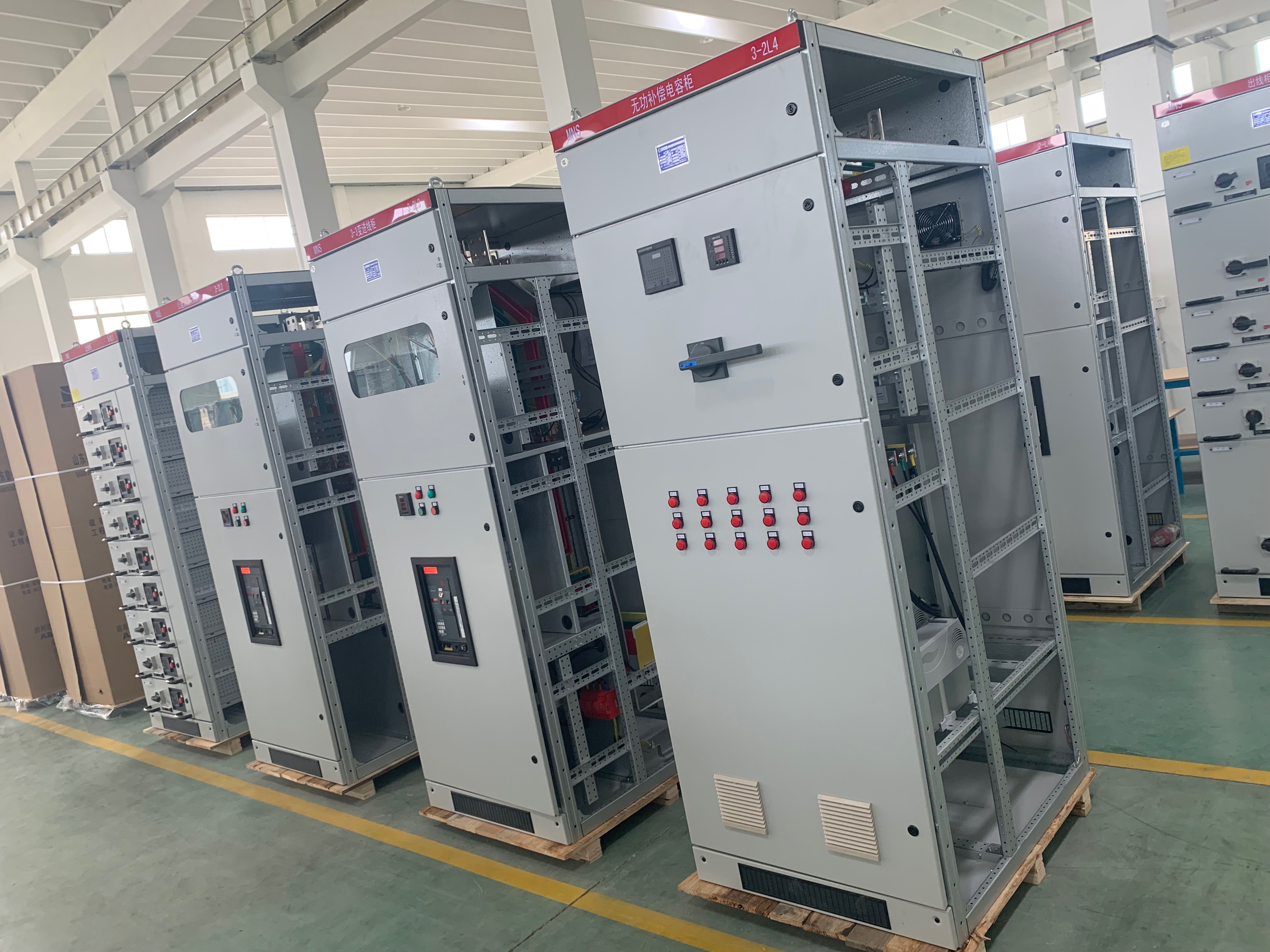
An MCC Motor Control Center is a low-voltage motor control and distribution system, typically used in 0.4kV low-voltage systems for centralized control of motors such as fans, pumps, mixers, conveyors, and other industrial equipment.
MCC systems are generally divided into withdrawable MCCs and fixed-compartment MCCs.
Withdrawable units can be disconnected, removed, and replaced individually, allowing maintenance without shutting down the entire MCC section. Fixed-compartment MCCs generally have a lower initial cost and are suitable for circuits that do not require frequent maintenance.
The core components typically include:
Main busbar
Vertical distribution busbar
Withdrawable units
Circuit breakers
Contactors
Thermal overload relays / motor protection relays
Enclosure
Secondary control circuits
Compared with conventional GGD low-voltage distribution cabinets, MCCs provide a higher number of motor control circuits and a modular unit configuration, making them particularly suitable for production facilities with a high density of motor loads.
However, because MCC cabinets have a relatively high internal component density, busbar design and heat dissipation are critical factors during selection.
The main busbar carries the total incoming current of the MCC system. Its rated current should be determined based on the rated current of the transformer’s low-voltage side, combined with the expected simultaneous load factor and an appropriate design margin.
For example:
For a 1600kVA transformer, the rated current on the low-voltage side is approximately 2300A. In this case, a 2500A main busbar may be selected for the MCC, subject to the actual load calculation and applicable design requirements.
The vertical distribution busbar inside each MCC section must be capable of carrying the maximum simultaneous operating current of all outgoing circuits in that section.
This is an important point that is sometimes overlooked in low-cost MCC configurations. Some manufacturers provide an adequately sized main busbar while undersizing the vertical busbar. When multiple motors start or operate simultaneously, the undersized vertical busbar may experience excessive temperature rise and eventually fail.
In a pharmaceutical production workshop, one MCC section controlled eight high-power mixing motors operating simultaneously. The vertical busbar was rated at 630A, while the actual maximum operating current reached 720A.
After approximately three months of operation, the vertical busbar experienced severe overheating. The withdrawable-unit plug-in contacts melted, causing several motors to shut down. The production line was forced to stop for six days for inspection and repairs, resulting in an estimated loss of RMB 210,000.
Key lesson: The vertical distribution busbar must not be overlooked. The maximum simultaneous operating current of all loads in the MCC section should be calculated, with an appropriate design margin—25% or more where justified by the project requirements.
Common MCC withdrawable unit configurations include 1/4-unit, 1/2-unit, 1-unit, and 2-unit designs.
The appropriate unit size should be selected according to the motor power, starting characteristics, protection devices, and internal heat dissipation requirements.
High-power motors should not be forced into undersized withdrawable units simply to save cabinet space. Insufficient internal space can restrict heat dissipation and increase the risk of component overheating.
Common short-time withstand current ratings include 10kA, 15kA, and 25kA, depending on the system short-circuit level and equipment design.
For chemical plants and large-capacity industrial facilities with higher prospective short-circuit currents, a 25kA short-time withstand rating may be considered where required by the system calculation.
The withstand capability of the complete MCC assembly—including the cabinet, busbars, withdrawable units, and associated components—must be properly coordinated.
For conventional fan and pump applications, thermal overload relays can generally provide basic overload protection.
For heavy-duty motors, frequent-starting applications, or critical production equipment, intelligent motor protection relays are recommended. These devices can provide functions such as:
Overload protection
Phase-loss protection
Overcurrent protection
Ground-fault protection
Motor operating status monitoring
A chemical plant used a 90kW high-power pump. To reduce cabinet space, the project selected a 1/2-unit withdrawable module.
The pump operated at a high load for extended periods. Due to the limited internal space and poor heat dissipation, the contactor inside the withdrawable unit overheated and eventually welded closed. The motor could no longer be properly disconnected, resulting in damage to the pump.
Corrective action: The 1/2-unit module was replaced with a larger 2-unit withdrawable unit, providing additional internal space and improved heat dissipation.
Thermal management should be evaluated according to the load density and operating environment of the MCC.
For ordinary industrial workshops, natural ventilation may be sufficient. Ventilation louvers can be installed on the cabinet doors to facilitate heat dissipation.
For MCCs containing multiple heavy-load circuits or installed in workshops with high summer temperatures, roof-mounted cooling fans and forced ventilation may be required.
For underground substations and enclosed electrical rooms, adequate room ventilation should be provided to prevent heat accumulation inside and around the MCC cabinets.
For workshops with high levels of dust or industrial contaminants, ventilation openings should be equipped with dust filters and maintained regularly to prevent contamination from entering the cabinet.
Typical enclosure protection levels may include:
IP30: Standard indoor environments
IP41: Workshops with higher dust exposure
IP42: Damp indoor environments
The actual IP rating should be selected according to the installation environment and project requirements.
For intelligent MCC systems, Modbus communication can be configured to transmit motor operating parameters, current values, fault signals, and other information to the plant DCS system.
This enables centralized monitoring and facilitates predictive maintenance and fault diagnosis.
For coastal environments exposed to salt spray, the cabinet should receive appropriate anti-corrosion treatment and protective coating.
For hazardous areas, MCC equipment must be selected and designed according to the applicable explosion-protection requirements and hazardous-area classification.
Ignoring the vertical distribution busbar can result in local overheating and busbar failure.
Forcing large motors into small withdrawable units can lead to insufficient internal space and poor heat dissipation.
If the cabinet, busbars, and withdrawable units do not have coordinated short-circuit withstand capabilities, a short-circuit fault may cause serious damage to individual units.
MCCs with multiple heavy-load circuits may require forced ventilation. Without adequate thermal management, high summer temperatures can increase the risk of overheating and nuisance tripping.
Standard MCC configurations may not be suitable for environments with high dust, moisture, or corrosive gases. Appropriate enclosure protection, surface treatment, filtration, or specialized equipment should be considered.
MCC Motor Control Center selection should not be based solely on the number of outgoing circuits.
The main and vertical busbars determine the overall current-carrying capability of the MCC. Withdrawable unit size must match the motor power and heat dissipation requirements. Short-circuit withstand capability determines the MCC’s ability to withstand fault currents, while thermal management is essential for long-term stable operation.
For standard industrial motor loads, a conventional withdrawable MCC can provide an efficient and modular solution. For chemical plants and heavy-duty industrial applications, higher short-circuit withstand capability, larger withdrawable units, and forced ventilation may be required.
MCC selection should comply with GB 7251.1 and applicable project standards while taking into account motor power, simultaneous operating factors, prospective short-circuit current, installation conditions, and environmental requirements.
A properly engineered MCC can help prevent overheating, component failure, unplanned shutdowns, and the resulting production losses.
Hengfengyou Electric provides MCC Motor Control Centers, GGD low-voltage switchgear, and low-voltage power distribution panels, with customized solutions based on customer motor lists. Our engineering team can assist with outgoing circuit arrangement, busbar current calculations, withdrawable unit configuration, and MCC system design.
Email: hunter@hengfengyou.com
WhatsApp/Mobile: +86 182 2442 9139
WhatsApp:
+86 13969788801
+86 15853252696
Tel:+86-0532-68688801
Fax:+86-0532-87038801
Email: hfy@hengfengyou.com
Address: No.638,Zhongcheng Road, Chengyang District, Qingdao City,China
Leave a message now - get the latest industry insights, star products, and success stories of hengfengyou electric